Transcription of 119 Series Fuel Gas Valve - Emerson
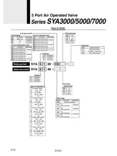
1 119 Series fuel Gas ValveContentsIntroduction ..4 Specifications ..2 Description ..4 Principle of Operation ..4 Installation ..5 Startup ..6 Speed Adjustment ..6 Spring Adjustment ..6 Shutdown ..7 Maintenance ..7 Disassembly ..7 Assembly ..8 Parts Ordering ..8 Parts List ..8 Figure 1. 119 Series fuel Gas ValveType 119 Type 119eZ!WarninGFailure to follow these instructions or to properly install and maintain this equipment could result in an explosion, fire and/or chemical contamination causing property damage and personal injury or valves must be installed, operated and maintained in accordance with federal, state and local codes, rules and regulations and Emerson process Management regulator Technologies, inc. ( Emerson ) the Valve vents gas or a leak develops in the system, service to the unit may be required.
2 Failure to correct trouble could result in a hazardous , operation and maintenance procedures performed by unqualified personnel may result in improper adjustment and unsafe operation. either condition may result in equipment damage or personal injury. Call a qualified personnel when installing, operating and maintaining the 119 Series Manuald100261X012 June 2018119 SeriesSpecificationsThe Specifications table lists the specifications for the 119 series fuel gas valve . Some of the specifications of the given Valve that originally comes from the factory, are stamped on the nameplate located on the spring case The pressure/temperature limits in this Instruction Manual, ASCO solenoid documentation and any applicable standard or code limitation should not be Pressure and/or the body end connection may decrease these maximum Not for use with hot water or Ammonia (NH3).
3 4. Minimum temperature for Cast Iron body is -20 F / -29 Configuration Type 119: Direct-operated Valve used for on-off or throttling control of noncorrosive or mildly corrosive liquids and gases Type 119eZ: Direct-operated Valve with adjustable opening speed for reliable startup operation on gas burner systems Type 119eZS: Type 119EZ equipped with solenoid for Valve to be operated by local control system Body Sizes and end Connection StylesType 119:Body SiZe, npTBody MaTerial3/4 Cast Iron, WCC Steel11-1/4 Cast IronTypes 119eZ and 119eZS:Body SiZe, npTBody MaTerial1 Cast Iron, CF8M Stainless SteelSpring rangesSee Table 1 Orifice Size and Flow CoefficientsSee Table 2 Maximum inlet pressure(1)150 psig / barMaximum Control pressure to diaphragm150 psig / barMaximum pressure drop(1)150 psig / bar for all port diameters 115 psig / bar for Type 119 EZS with ASCO 8320 Series solenoidpressure Setting adjustmentMay be adjusted throughout each spring rangeby rotating the adjusting screwType 119 EZS Solenoid Specifications Electric Train: Refer to ASCO 8320 Series General Service Solenoid Valve Catalog (Document Number: 8320R2) Low Power/Solar: Refer to ASCO Low Power Solutions Catalog (Document Number: V7704) Valve plug Travel3/16 in.
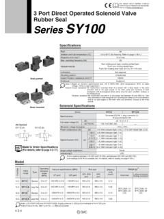
4 / mmactuator Control line Connection1/4 FNPTS pring Case and Bonnet Vents1/4 FNPTFlow directionUp through the orificeMaterial Temperature Capabilities(1)(2)Type 119:MaTerialTeMperaTure ranGeNitrile (NBR)-20 to 180 F / -29 to 82 CFluorocarbon (FKM)(3)0 to 250 F / -18 to 121 CTypes 119eZ and 119eZS:MaTerialTeMperaTure ranGeNitrile (NBR)(4)-40 to 180 F / -40 to 82 CFluorocarbon (FKM)(3)0 to 250 F / -18 to 121 CType 119eZS Solenoid Temperature Capabilities(1)aSCo 8320 Series Solenoid:32 to 125 F / 0 to 52 CaSCo 8314 Series Solenoid:-13 to 131 F / -25 to 55 CConstruction MaterialsStandard ConstructionValve Body: Cast iron, WCC steel or Stainless steelSpring Case: AluminumBonnet: AluminumDisk Holder Assembly: Aluminum and Nitrile (NBR)(standard), Stainless steel and Nitrile (NBR) orStainless steel and Fluorocarbon (FKM)Orifice: Aluminum (standard) or Stainless steelDiaphragm: Nitrile (NBR) or Fluorocarbon (FKM)O-rings: Nitrile (NBR) (standard) or Fluorocarbon (FKM)Stem Wiper: Polytetrafluoroethylene (PTFE)Adjusting Screw: SteelSpring: SteelnaCe ConstructionBody: Steel or Stainless steel Disk Holder Assembly: Aluminum or Fluorocarbon (FKM)Diaphragm and Stem Assembly: Aluminum or Fluorocarbon (FKM)O-rings and Internal Retaining Rings:Fluorocarbon (FKM)approximate Weight6 lbs / 3 kg2119 SeriesTYPEORIFICE SIZE - RANGE - PSIMATERIALCODEF igure 2.
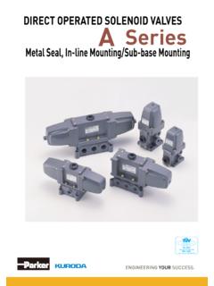
5 119 Series NameplateFigure 3. Types 119EZ and 119 EZS Valve Opening Restrictor Adjustment with 50 psig / bar Inlet PressureMaTerialCodeoriFiCeSeaT diSk MaTerialAI/NSST/NSST/VAluminum/Nitrile (NBR)Stainless steel/Nitrile (NBR)Stainless steel/Fluorocarbon (FKM)SprinG ranGeSprinG parT nuMBerSprinG Color CodeFree lenGThWire to to .275 to to .755 to to .5430 to to 1. Spring SCREW TURNS COUNTER-CLOCKWISE FROM FULLY ENGAGEDOPENING SPEED IN SeriesINLET PRESSUREOUTLET PRESSUREATMOSPHERIC PRESSURELOADING PRESSURE introductionScope of the ManualThis instruction manual provides installation, spring adjustment, maintenance and parts information for the 119 Series 119 Series Valve (Figure 1) is used for on-off or throttling control of noncorrosive or mildly corrosive flow media.
6 It is designed to meet low-pressure application requirements in many varied of operation119 SeriesAs loading pressure is applied to the 119 Series Valve diaphragm, the disk holder is pulled off the orifice. As loading pressure is reduced, the opposing spring force moves the disk holder toward the closed position, resulting in spring-close action should a loss of loading supply pressure Type 119EZ comes equipped with an adjustment tool that can be used to modulate the Valve opening speed, while still allowing for quick closing speeds. The Type 119 EZS comes equipped with a solenoid control Valve that opens and closes based on signal responses from the burner management Management SystemA Burner Management System (BMS) is a safety solution for Oil and Gas facilities that enables the safe start-up, operation and shut down of the burner section of a fire tube vessel.
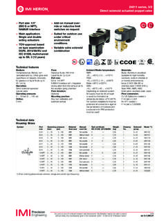
7 It reduces maintenance, improves up-time and provides a safe environment for fire tube vessels and field pressure control elements are essential to ensure a safe and efficient burner system. A burner pressure regulator needs to be able to open slow during startup, close fast during shutdown and throttle to maintain temperature during normal operation. Poor main burner pressure regulation contributes to an inefficient fuel gas pressure control system. Figure 4. 119 Series Operational SchematicsINLET PRESSUREOUTLET PRESSUREATMOSPHERIC PRESSURELOADING PRESSUREType 119 Type 119eZ(1)Type 119M1033 July 2007 Type 119M1033_07/20071. Solenoid Valve connects to loading pressure PRESSUREOUTLET PRESSUREATMOSPHERIC PRESSURELOADING PRESSURE4119 SeriesIn addition, if the main burner regulators require frequent monitoring, maintenance and replacement, increased operation and maintenance costs could be simplifies the complexity of fuel gas pressure control system by providing a one-stop solution, eliminating procurement challenges.
8 Emerson s solution works with a BMS to ensure efficient burner ignition/re-ignition, shutdown and steadily throttles to maintain temperature during normal operation. The solution is proven and robust, thereby significantly lowering maintenance expenses. installation!WarninGTo avoid personal injury or property damage caused by controlled process fluid or bursting of pressure-retaining parts, be certain the service conditions do not exceed the limits shown in Specifications section. The leak-off and spring case vents must be kept open. To avoid danger of fire or explosion from venting of flammable or otherwise hazardous fluid into a closed or poorly vented location, pipe the vents to a well-ventilated location, away from any buildings or windows so as not to create a further Before installing the Valve , be sure the Valve body and associated equipment are free of damage and foreign.
9 The Valve can be installed in any position, but the normal orientation is with the actuator portion vertical above the body. If installing the Valve at an outside location, point the spring case and bonnet vents in the downward direction to protect them from moisture or foreign . Install the Valve using accepted piping practices. Make sure that the Valve is oriented so that flow through the body will match the flow direction arrow on the . If continuous operation is required during maintenance and inspection, install a three- Valve bypass around the 5. Burner Management Operational SchematicsLPSD# #1** OptionalSSSSINLET PRESSUREMEDIUM / LOW PRESSURELOADING PRESSUREFuel GaS627 SerieS67C SerieSBurner ManaGeMenT67 CSerieSySSolenoid ValVeeMerGenCy ShuTdoWn Valve Main BurnerpiloT BurnerMain Burner ValVepiloT Burner reGulaTor piloT Solenoid ValVeSolenoid ValVeMain Burner reGulaTor119eZ SerieSType 119loadinG preSSure reGulaTorLPSD# #1** OptionalSSSSINLET PRESSUREMEDIUM / LOW PRESSURELOADING PRESSURE*Optional5119 Series5.
10 Connect the control pressure line to the 1/4 NPT connection in the Valve body bonnet marked 150 psig / bar max .6 . For Type 119 EZS, wire the solenoid per the solenoid wiring instructions, Document Number: 8320R2, for the standard ASCO 8320 Series solenoid using 24V DC power. Wire the low power ASCO 8314 Series solenoid per Document Number: V7704. Wiring must comply with applicable local, state and federal codes and the National Electric !WarninGThe maximum inlet, differential and outlet pressures should never be exceeded during startup. use pressure gauges to monitor inlet pressure, outlet pressure and any loading pressure during Check that proper installation is completed and upstream and downstream equipment has been properly . Make sure all block and vent valves are.