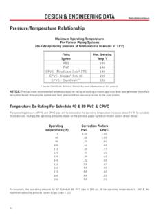
Transcription of 12. Allowable Joint Deflections. - WSSC Water
1 Part One, Section 12. Allowable Joint Deflections Water DESIGN GUIDELINES 2008 12. Allowable Joint Deflections. a. General. 1) When it is necessary to deflect pipe from a straight line in either the horizontal or vertical plane, the amount of Joint deflection shall not exceed the Allowable Joint deflections as shown in Tables "3", " ", "4", " ", " ", " ", " " and " ". Figure "A" illustrates the Joint deflections shown in the tables. The deflections listed in the tables are the maximum deflections Allowable for wssc pipeline designs and should not be exceeded.
2 Assume twenty (20) foot lengths of pipe for design purposes. b. DIP and PVC with Push-on Type Joints. 1) For maximum Joint deflections for full-length DIP with push-on type joints, see Table "3". The maximum deflection angles shown in Table "3" are used for design purposes and are based on eighty (80%) percent of the maximum recommended deflection for standard pipe joints that all DIP manufacturers can produce. The eighty (80%) percent value is based on AWWA C600 recommendations. 2) DIP manufacturers can produce pipe with larger Joint deflections or special pipe joints with larger deflections.
3 If the design requires larger deflections then those shown in Table "3", submit information for approval. TABLE "3" Deflection Table - DIP Push-on Type Joints Nominal pipe Size Diameter (D) Maximum Offset Based on 20 Foot Lengths of pipe (S) Design Maximum Deflection Angle (0) Minimum Allowable Radius (R) 12-inch and under feet 04 -00' ( ) 290 feet 14-inch and over feet 02 -24' ( ) 480 feet 3) For maximum Joint deflections for full-length PVC pipe with push-on type joints on pipelines which are 12-inches and smaller in diameter, see Table " ". The maximum deflection angle in Table " " is used for design and is based on seventy (70%) percent of the recommended deflection for standard pipe joints that most PVC manufacturers can produce.
4 4) No deflection at connection to DIP or at fittings. 5) Only pipe Joint deflections are allowed at Joint , no bending of the pipe . TABLE " " Deflection Table - PVC pipe with Push-on Joints Nominal pipe Size Diameter (D) Maximum Offset Based on 20 Foot Lengths of pipe (S) Design Maximum Deflection Angle (0) Minimum Allowable Radius (R) 12-inch and under feet 01 -24' ( ) 820 feet Part One, Section 12. Allowable Joint Deflections Water DESIGN GUIDELINES 2008 c. DIP Mechanical Joints. 1) For maximum Joint deflections on full-length DIP mechanical Joint pipe , see Table "4".
5 The maximum deflection angle in Table "4" is used for design purposes and is based on eighty (80%) percent of the maximum recommended deflection set by wssc for pipe sizes 20-inch and smaller and on AWWA C600 for 24-inch pipe . The eighty (80%) percent value is based on AWWA C600 recommendations. 2) Mechanical Joint pipe may not be available, therefore verify the availability of Mechanical Joint pipe with the pipe manufacturers before specifying this type of pipe in the design. TABLE "4" Deflection Table - DIP Mechanical Joint pipe Nominal pipe Size Diameter (D) Maximum Offset Based on 20 Foot Lengths of pipe (S) Design Maximum Deflection Angle (0) Minimum Allowable Radius (R) 12-inch and under feet 04 -00' ( ) 290 feet 14-inch to 20-inch feet 02 -24' ( ) 480 feet 24-inch feet 01 -36' ( ) 720 feet d.
6 Restrained Joint pipe . 1) For maximum Joint deflections on full length restrained Joint DIP or PVC pipe , see Tables " ", " ", " ", " ", " " and " ". 2) The types of restrained Joint pipe and fittings in the tables below are the wssc approved restrained joints ( pipe or fittings) which are included in the Standard Details and the Specifications. First consider using concrete thrust blocking before specifying restrained joints, see Part Three, Section 27 (Thrust Restraint Design for Buried Piping). 3) Indicate on the drawings the limits of restrained joints in the Blocking Notes and on the profile.
7 4) Type of restrained joints: a) Wedge action-restraining glands on DIP mechanical Joint pipe . (1) For maximum Joint deflections for full length restrained mechanical Joint pipe with wedge action restraining glands, see Table " ". The maximum deflection angle in Table " " is used for design purposes, and is based on eighty percent (80%) of the maximum recommended deflection set by wssc for pipe sizes 20-inch and smaller and on AWWA C-600 for 24-inch diameter pipe . (2) Maximum size of wedge action restraining glands for fittings is 48-inch diameter. Mechanical Joint pipe is only available in pipe sizes 24-inch and smaller diameter, therefore verify the availability of 14-inch to 24-inch Mechanical Joint pipe with the mechanical Joint pipe manufacturers before specifying in the design.
8 (3) Only use wedge action restraining glands when the total pressure (operating pressure plus surge pressure) is below the pressures in Table " ". Part One, Section 12. Allowable Joint Deflections Water DESIGN GUIDELINES 2008 (4) Wedge action restraining glands can only be used for DIP, see Standard Detail TABLE " " Deflection Table - Wedge Action Restraining Glands - Mechanical Joint DIP Nominal pipe Size Diameter (D) Maximum Offset Based on 20 Foot Lengths of pipe (S) Design Maximum Deflection Angle (0) Minimum Allowable Radius (R) 12-inch and under feet 04 -00' ( ) 290 feet 14-inch to 20-inch feet 02 -24' ( ) 480 feet 24-inch feet 01 -36' ( )
9 720 feet TABLE " " Maximum Total Pressure for Wedge Action Restraining Glands for DIP Nominal pipe Size Diameter (D) Total Pressure (Operating Pressure plus Surge Pressure) 16-inch and smaller 350 psi Larger than 16-inch 250 psi b) Push-on restrained Joint gaskets for DIP, 24-inch and smaller diameter. (1) Maximum Joint deflections for full-length manufacturer's proprietary restrained Joint DIP, see Table " ". Maximum deflection angle for design is based on eighty (80%) percent of the maximum recommended deflection angle set by wssc for pipe sizes 24-inch and smaller in diameter. TABLE " " Deflection Table - Manufacturer's Proprietary Restrained Joint DIP - Push-on Restrained Joint Gaskets Nominal pipe Size Diameter (D) Maximum Offset Based on 20 Foot Lengths of pipe (S) Design Maximum Deflection Angle (0) Minimum Allowable Radius (R) 12-inch and under feet 04 -00' ( ) 290 feet 14-inch to 24-inch feet 02 -24' ( ) 480 feet c) Manufacturer's proprietary restrained joints for DIP, 14-inch and larger diameter.
10 (1) For maximum Joint deflections for full-length manufacturer's proprietary restrained Joint DIP, see Table " ". The maximum deflection angle in Table " " is used for design purposes and is based on eighty (80%) percent of the manufacturer s recommended deflection angle. (2) Manufacturers produce other types of restrained pipe and fittings, which are not included in the Specifications and Standard Details. These restrained joints may be specified if approved. Part One, Section 12. Allowable Joint Deflections Water DESIGN GUIDELINES 2008 TABLE " " Deflection Table - Manufacturer's Proprietary Restrained Joint DIP Nominal pipe Size Diameter (D) Maximum Offset Based on 20 Foot Lengths of pipe (S) Design Maximum Deflection Angle (0) Minimum Allowable Radius (R) 14-inch to 16-inch feet 02 -24' ( ) 480 feet 18-inch to 30-inch feet 01 -24' ( ) 820 feet 36-inch to 54-inch feet 00 -24' ( ) 2860 feet d) Wedge action-restraining glands for DIP push-on joints.