Transcription of 12. VIBRATION ISOLATION - Penn State …
1 NOISE CONTROL VIBRATION ISOLATION J. S. Lamancusa Penn State 5/28/2002 12. VIBRATION ISOLATION Introduction High VIBRATION levels can cause machinery failure, as well as objectionable noise levels. A common source of objectionable noise in buildings is the VIBRATION of machines that are mounted on floors or walls. Obviously, the best place to mount a vibrating machine is on the ground floor. Unfortunately (but fortunately for noise control consultants), this is not always possible. A typical problem is a rotating machine (such as a pump, AC compressor, blower, engine, etc) mounted on a roof, or on a floor above the ground floor. The problem is usually most apparent in the immediate vicinity of the VIBRATION source.
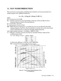
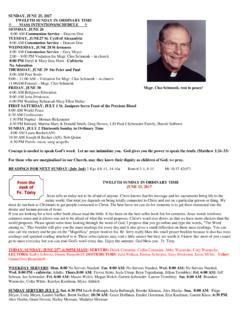
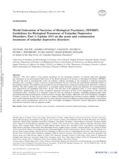
2 However, mechanical vibrations can transmit for long distances, and by very circuitous routes through the structure of a building, sometimes resurfacing hundreds of feet from the source. A related problem is the ISOLATION of VIBRATION -sensitive machines from the normally occurring disturbances in a building (car or bus traffic, slamming doors, foot traffic, ). Examples of sensitive machines include surgical microscopes, electronic equipment, lasers, MRI units, scanning electron microscopes, and computer disk drives. Figure 1 shows a common example of a VIBRATION source, a large reciprocating air conditioning compressor weighing 20,000 pounds, mounted on a roof. Annoying noise levels at multiples of the compressor rotational frequency, predominantly 60 and 120 Hz, were measured in the rooms directly below the compressor.
3 For whatever reason (don t get me ), the architect chose to mount this unit at the middle of the roof span, at the midpoint between supporting columns. Also, this type of compressor (reciprocating) is notorious for high VIBRATION levels. Centrifugal or scroll type compressors are much quieter, but more expensive (you get what you pay for!). Figure 1. A reciprocating air conditioning compressor and chiller mounted on a flexible roof, Note the straight conduit on the left which bypasses the isolators and directly transmits VIBRATION into the roof NOISE CONTROL VIBRATION ISOLATION J. S. Lamancusa Penn State 5/28/2002 A VIBRATION problem can also be nicely described by the same source path receiver model we previously used to characterize the noise control problem.
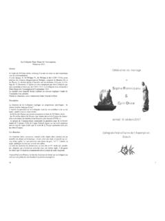
4 Source: a mechanical or fluid disturbance, generated internally by the machine, such as unbalance, torque pulsations, gear tooth meshing, fan blade passing, etc. These typical occur at frequencies which are integer multiples of the rotating frequency of the machine. Path: the structural or airborne path by which the disturbance is transmitted to the receiver Receiver: the responding system, generally having many natural frequencies which can potentially be excited by VIBRATION frequencies generated by the source. (Murphy says the natural frequency of the system will always coincide with an excitation frequency.) Any or all of these areas can be attacked to solve the problem. The best choice for a given application will be dictated by the laws of physics, your ingenuity, and $.
5 References: Sources of additional information on VIBRATION ISOLATION include: Manufacturer s technical data check the web or catalog data sheets, some suppliers include: o Mason Industries o Barry Controls o Kinetics ASHRAE (American Society of Heating, Refrigeration and Air Conditioning Engineering) Applications Handbook, 1999. See Appendix Handbook of Acoustical Measurements and Noise Control, Cyril M. Harris, McGraw Hill, 1991. Noise and VIBRATION Control Engineering, L. Beranek editor, John Wiley and Son, 1992, pp 429-450 RECEIVER PATH SOURCE NOISE CONTROL VIBRATION ISOLATION J. S. Lamancusa Penn State 5/28/2002 Possible Solutions The best solution to a VIBRATION problem is to avoid it in the first place.
6 Intelligent design is far more cost effective than building a bad design and having to repair it later. The intelligent solution to any VIBRATION problem involves the following steps: 1) Characterize the system parameters (mass, stiffness, damping) by experimental methods, manufacturers data, or a combination of both. 2) Model the system dynamics using a simple lumped parameter model a) identify natural frequencies, look for coincidence with excitation frequencies b) if excitation forces and frequencies are known, system response can be calculated 3) Use the model to assess the effect of changes in system parameters VIBRATION Solutions - Source 1) Relocate machine place machine on as rigid a foundation as possible (on grade is best) and as far as possible from potential receivers 2) Replace machine with a higher quality or different type of machine that is quieter (and probably more expensive) 3)
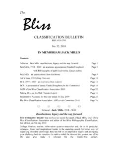
7 Change the operating speed of the unit to avoid coinciding with structural resonances 4) Balance rotating elements, 5) Add a tuned VIBRATION absorber 6) Use active VIBRATION control VIBRATION Solutions - Path Minimizing the VIBRATION transmission generally involves using isolator springs and/or inertia blocks. The basic principle is to make the natural frequency of the machine on its foundation as far below the excitation frequency as possible. The mathematics for this case, and isolator selection procedures are discussed in the next sections. VIBRATION Solutions Receiver 1) Change the natural frequencies of the system to avoid coinciding with excitation frequencies. This can be accomplished by adding stiffeners (which raises the natural frequency) or by adding mass (which lowers the natural frequency) 2) Add structural damping VIBRATION Isolators Consider a vibrating machine, bolted to a rigid floor (Figure 2a).
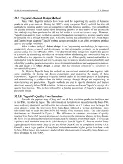
8 The force transmitted to the floor is equal to the force generated in the machine. The transmitted force can be decreased by adding a suspension and damping elements (often called VIBRATION isolaters) Figure 2b , or by adding what is called an inertia block, a large mass (usually a block of cast concrete), directly attached to the machine (Figure 2c). Another option is to add an additional level of mass (sometimes called a seismic mass, again a block of cast concrete) and suspension (Figure 2d). NOISE CONTROL VIBRATION ISOLATION J. S. Lamancusa Penn State 5/28/2002 a) b) c) d) Figure 2.
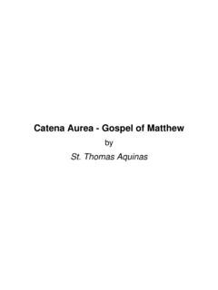
9 VIBRATION ISOLATION systems: a) Machine bolted to a rigid foundation b) Supported on ISOLATION springs, rigid foundation c) machine attached to an inertial block d) Supported on ISOLATION springs, non-rigid foundation (such as a floor); or machine on ISOLATION springs, seismic mass and second level of isolator springs If we consider only the vertical motion, the case shown in Figure 2b can be described mathematically by a single degree of freedom, lumped element system. )(..tFkxxcxm=++ Equation 1 where: m = mass of system k = stiffness c = viscous damping x(t) = vertical displacement F(t) = excitation force If we neglect damping, the vertical motion of the system, x(t) can be shown to be: mkrtrkFtxnnO== = :re whesin1)(2 Equation 2 The system has a natural, or resonant frequency, at which it will exhibit a large amplitude of motion, for a small input force.
10 In units of Hz (cycles per second), this frequency, fn is: mkfnn 212== Equation 3 In units of RPM (revolutions per minute), the critical frequency is mkfRPMncritical 26060== The force transmitted to the floor is:kxFT= The ratio of transmitted force to the input force is called transmissibility, T YXrFFTOT= ==112 Equation 4 This same equation can also be used to calculate the response of a machine X to displacement of the foundation, Y. The effectiveness of the isolator, expressed in dB is: Transmitted Force FT(t) Input Force F(t)=Fosin t x(t) INERTIA BLOCK MACHINE SEISMIC MASS ISOLATOR SPRINGS y(t) NOISE CONTROL VIBRATION ISOLATION J.