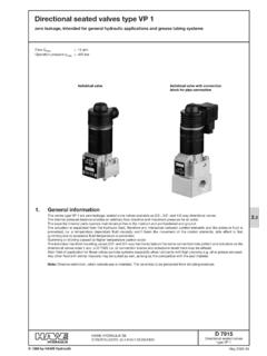
Transcription of 2/2- and 3/2-way directional seated valves type …
1 2/2- and 3/2-way directional seated valves type BVG and BVPfor any flow direction, zero leakage all ports pressure resistantD 7400 seated valves type BVG(P) 3 January 2007-03 HAWE HYDRAULIK SESTREITFELDSTR. 25 81673 M 1987 by HAWE HydraulikPerm. pressure pmax= 320 barPerm. flow Qmax= 50 lpmAdditional valves with same function:'Type BVG 11(12 and 2), BVP 11(2) see appendix, sect. , Run-out design do not use for new layouts!'Type BVG , BVP 1 D 7765(Qmax= 20 lpm, pmax= 400 bar)'Type NBVP 16D 7765 N (Qmax= 20 lpm, pmax= 400 bar)'Type BVE D 7921(Qmax= 70 lpm, pmax= 400 bar)'Type VPD 7915(Qmax= 15 lpm, pmax= 400 bar)Design for pipeconnectionExample: Type BVG 3 S-G 24 Design for manifold mountingExample: Type BVP 3 R-G 2/2- and 3/2-way directional cone seated valves are available with electrical, hydraulic or pneumatic actuation.
2 All ports areequally pressure resistant due to the internal pressure zero or idle position is achieved automatically if the valve is not actuated due to spring return. They are of all steel design andall functionally essential internal parts are hardened and run maintenance free in oil; Cones and seats are 7400 page 2 BVP 3 Z - H 1/4 BVP 3 R(S) - H 1/4 BVP 3 Z - PBVP 3 R(S) - versions, main dataOrder examples:BVG 3 R/B 2,5 - WG 230 BVP 3 Z- PComplete symbols (The actuation symbols applyto all flow symbols)Pipe connectionBVG 3 R - H BVG 3 S - PBVG 3 Z - 3 Z - mountingTable 2: SymbolsRSZT able 1: Basic type and size 1)CodingBVG 3 BVP 3 Design and connectionPipe connection G 1/2 ISO 228/1(BSPP)Manifold mountingFlowQmax(lpm)5050 Pressurepmax(bar)320320 BVP 3 Z - HBVP 3 R(S) - HBVP 3 Z - 3 Z - 3:Orifices(in ports A, B, and C, see also sect.
3 CodingNo. for subsequent ordersSystem or accumulator (mm)BVG rangeB 2, 014 b7405 013 babout 300 barB 337405 014 c7405 013 cabout 200 barB 3, 014 d7405 013 dabout 150 barB 447405 014 e7405 013 eabout 100 bar2)02)7405 014 a7405 013 a--1) Type BVG 11(12, 2) and BVP 11(2) see appendix, sect. , Run-out design do not usefor new layouts!2) Undrilled for customized diameter acc. to |p-Q-curve of the orifices, sect. ) DC-solenoid (98 V DC, 205 V DC) with plug featuring a bridge rectifier circuitTable 4: ActuationsMain data, see also sect. 12 V DCUN= 24 V DCUN= 110 V AC, 50/60 Hz (98 V DC) 3)UN= 230 V AC, 50/60 Hz (205 V DC) 3)Ext. control port G 1/4 (BSPP). Onlywith type BVP 3 !Ext. control port G 1/4 (BSPP)with plugG 12G 24WG 110WG 230HH 1/4 PCodingPlug withLEDL 12L 24------withoutplugX 12X 24X 98X 205 SolenoidHydraulicPneumaticActuationContr ol pcontr min= 24 barpressure:pcontrmax= 320 barControl pcontr min= barpressure:pcontrmax= 15 barActuation SolenoidHydraulic Pneumatic symbolsCoding H 1/4 Coding H D 7400 page and hydraulicInstallation positionAnyNegative (transverse of one into the other flow direction is only completed when the switch-ing position is achieved).
4 All passages are interconnected during the switching pressurepmax=320 barStatic overload capacityPorts A, B, and C approx. 2 x pmax(640 bar)Body material and Steel, zinc galvanizedsurface coatingMass (weight) approx. kgPressure fluidHydraulic oil conforming DIN 51514 part 1 to 3: ISO VG 10 to 68 conforming to DIN limits: min. approx. 4, max. approx. 1500 mm2/s; opt. operation approx. 500 mm2 suitable are biological degradable pressure fluids types HEPG (Polyalkylenglycol) andHEES (Synth. Ester) at service temperatures up to approx. +70 : approx. -40 .. +80 CFluid: -25 .. +80 C, Note the viscosity range !Permissible temperature during start: -40 C (Observe start-viscosity!), as long as the service temperature is at least 20K higher for the following degradable pressure fluids: Note manufacturer s specifications. By considerationof the compatibility with seal material not over +70 : Observe the restriction regarding the operation duration in sect.
5 !Perm. flowQpermacc. to sect. 2 applies to pmax= 320 bar with solenoid actuation in usual pump pressure < 150 bar (solenoid actuated) or with all other actuation modes Qpermmay beexceeded up to 50% as long as the back pressure is permissible. Flow limitationThe max. flow has to be limited (depending on the pressure) by means of orifices in the caseof accumulator circuits or if connected to high pressure circuits (circulation lines or centralsupplies) down to the specified Qmax(see sect. 2). These orifices must be located always on the accumulator side. With valves type .. theyare installed in port C. If mounting in port A or B is requested, this has to stated in uncoded text. For detailed description see table 3, sect. with 3/2-waydirectional valvesCompletewith actuationSolenoidHydraulicPneumaticBVG 3 RBVG 3 3 3 RBVP 3 3 pressure|p (bar)Back pressure|p (bar)Flow Q (lpm)Flow Q (lpm)Viscosity of the oil during tests approx.
6 60 mm2/sAdditional orificesBasic valve|p-Q-curveD 7400 page solenoids are manufactured and tested conforming DIN VDE 0580DC-voltage AC-voltageCodingG 12G 24WG 110WG 230L 12L 24------X 12X 24------Nom voltageUN(V)1224110230 Nom. powerPN(W) (DC-voltage)(AC-voltage, 50/60 Hz)Switching time (guideline)ON or OFF: approx. 50 .. 60 ms; with approx. 2-3 times prolongedSwitchings / hourapprox. 2000/h to be regarded as approx. evenly distributedProtection classIP 65 (IEC 60529)(plug properly mounted)Insulation material classFContact temperatureapprox. 98 C, at 20 C ambient temperatureCut-off energyWA WsSurface coatingDIN 50961-Fe/Zn 12 bk cC(solenoid)Relative duty cycle during service (100% ED stampedon the solenoid)Rel. duty cycle %ED-5 minAmbient temp.}U( C)Pneumatic (Coding P)Hydraulic (Coding H, H 1/4)Type bar2 bar320 bar15 bar< 2bar---approx.
7 Pcontr max barapprox. pcontr max cm33 cm3 Steel (body)Light alloy (body)galv. zinc platedblack anodizedControl pressurePcontr minpcontr maxPerm. residual pressure in the control line for save returnto idle positionStatic over load capacity of ZControl oil volume (geom.)Housing material and surface coatingSolenoidterminalsPlug DIN EN 175 301-803 (circuitry and symbol)All plugs For additional plugs, see D 7163D 7400 page dimensionsAll dimensions are in mm and subject to change without notice! for pipe connectionIllustrations are with solenoid actuation (coding ), for other actuations see belowType BVG 3 R(S)Type BVG 3 ZFor missingdimensionssee below!Ports conf. ISO 228/1 (BSPP):A, B, and C = G 1/2 Ports conf. ISO 228/1 (BSPP): A and B = G 1/2 Hydraulic actuationCoding H 1/4 Pneumatic actuation Coding P emer-gency actuationCable gland aid (do not use any sharp-edged parts)1)Note: This dimension is depending on themanufacturer and can be up to max.
8 40 mm acc. to DIN EN 175 301-803!2) When required the solenoid may be rotat edto the valve body by another 4x90 in addition to the standard assembly positionillustrated here. Manual emergency actuationThe valve may be actuated by pressingdown the brass bolt visible from aboveby means of a steel pin or a screw driver :All pressure apparent at port Bloads on the cross section of thebrass bolt 100 bar or240 N !# 351)2)D 7400 page 6M6, 9 for manifold mountingIllustrations are with solenoid actuation (coding ), for other actuations see below BVP 3 R(S)M6, 7 deepHole pattern of the manifold (top view)Sealing of ports A, B, and C via NBR 90 ShPort Z: via O-ring NBR 90 ShAvailable as spare part, seal-kit DS 7400-3 incl. O-rings for actuation coding H, H 1 missingdata seesect. !For missingdata seesect.
9 !Type BVP 3 ZHydraulic actuationCoding HCoding H 1/4 Pneumatic actuationCoding P1) Control port Z is only apparent at versions with hydraulic actuationcoding H!Hole pattern of the manifold (top view)1)1)Control port Z is at theupper (valve section)D 7400 page BVG 11(12 and 2) or BVP 11(2)Run-out design do not use for new layouts! (Alternative, type BVG 1 and BVP 1 acc. to D 7765)Order examples:Symbols (see table 2 sect. 2) Attention:Symbol Z not available for type BVG 12 !BVG 11 R- G 24 BVP 2S/B 1,5 - WG 230 Table 5: Basic type and sizeCodingBVG 11 BVG 12 BVG 2 BVP 11 BVP 2 Design and connectionG 1/4G 3/8G 3/8 Manifold mountingFlowQmax(lpm)1220 1)201220 Pressurepmax(bar)320320 Table 6:Additional orifice (at ports A, B, and C, see also sect. )1) With solenoid actuation:20 lpm up to 200 bar12 lpm up to 320 bar and 80% EDsee also sect.
10 Flow 2) Undrilled for customized diameter acc. to |p-Q-curve of the orifices, sect. ) Only with type BVP 11(2), not available for (housing dimensions to small - radiation insufficient)Pipe connection ISO 228/1(BSPP)Table 7: Actuation modesActuationCoding, noteSolenoidG 12, L 12, X 12see table 4, G 24, L 24, X 24sect. 2WG 100, X 98WG 230, X 205G 24 EX3)Ex-proof designUN= 24 V DC; pmax= 220 bar !ManualAfor type BVG 11(12) !Body material and surface treat-ment = Steel (lever housing gas nitrated)Actuation torque= approx. 70 Nm at 320 barFurther parametersFor general and electrical data see sect. or (weight) approx. kgCompletewith actuationSolenoidManualBVG 11 R(S)BVG 12 R(S) 11 11 R(S) 11 actuationSolenoidBVG 2 R(S) 2 2 R(S) 2 |p-Q-curveBack pressure|p (bar)Back pressure|p (bar)Flow Q (lpm)Flow Q (lpm)Viscosity of the oil during tests approx.