Transcription of Pressure reducing valve type CDK
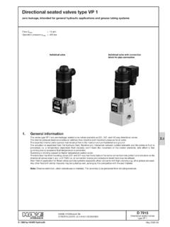
1 Pressure reducing valve type CDK 2/2-way designfor screwing into simple tapped holes (basic type)orcomplete with connection blocks for pipe connection or manifold mountingD 7745 Pressure reducing valve type CDK March 2009-00 1996 by HAWE HydraulikHAWE HYDRAULIK SESTREITFELDSTR. 25 81673 M versions' Pressure limiting valve type CMV, CSVD 7710 MV'Shut-off valve type CNED 7710 NE'Throttle and shut-off type CAVD 7711'Check valve type CRK, CRB, CRHD 7712' Pressure -dependent shut-off valves type CDSVD 7876'Throttle and restrictor check valves type CQ, CQR, and CQVD 7713'Flow control valves type CSJD 7736' Pressure reducing valves with tracked Pressure switch type DKD 7941 Utilized at: ' valve banks type VBD 7302' valve banks type BWH and BWND 7470 B/1' valve banks type BVZPD 7785 B' valve banks type BAD 7788' valve banks type BVHD 7788 BV'Intermediate plates size NG6, type NZPD 7788 ZPressurepmax P= 500 barpmax A= 500 barFlowQmax = 22 lpmBasic type (cartridge valve )Version with connec-tion block for directpipe connectionThe main purpose of Pressure reducing valves utilized in a hydraulic system is to maintain a rather constant Pressure on the consumer side(secondary Pressure ) even when the Pressure at the inlet side (primarypressure) is higher and common pressurereducing valves (spool design) require a return connection as there is always leakage.
2 Whereas type CDK is designed as a 2/2-way valve acting like a seated valve in idle type (Cartridge valves ):Type CDK 3 Standard version, usable for all CDK 32 Version with low Pressure dependence intended forvarying pump Pressure and use at low Pressure settings (Attention:Max. flow 6 lpm).Type CDK 35 Version with low back Pressure , but with higher sensivity to varying pump the characteristic differences of these valves , refer to table 1 in as well as " Pressure dependence" in sect. reversed flow A P ofthe open valve is possible as soon as the pres-sure on the primary side P drops below the one on the secondary side illustration of the symbol is with a check valve on this page. This isomitted for the sake of simplicity in the rest of the valves are to be screwed into simply shaped tapped holes of amanifold body. The sealing of the inlet to outlet takes place at the contact area between the facial sealing edge of the screwed-in end ofthe valve body and the stepped shoulder of the core diameter at the location thread.
3 Any standard steel drill (point angle 118 ) automatical-ly forms this stepped shoulder when the core diameter is drilled. There-fore reaming of the hole and bevels to help the seals slip in are not necessary. The sealing of the attached valve and its fixing at the manifold body are made by a sealing nut with a special thread seal andan with connection blocks:'For pipe connection (with/without Pressure limiting valve ) 'For manifold mounting (with/without Pressure limiting valve ) 'For manifold mounting (with/without Pressure limiting valve ) including adapter for direct pipe with con-nection block formanifold mountingD 7745 page 21) If no desired Pressure specification is indicated, the valve will be setat HAWE to the max. Pressure of the respective Pressure range2) The check valve function in direction A Pis not illustrated for thesake of simplicity (see description in sect. 1) versions, main type (cartridge valve )Example: Pressure specification (bar) forthe Pressure limiting valve with connection block for pipe connectionNote: For additional versions (together with manifold mounting valves ), see sect.
4 !Example:CDK 3 - 5 R- 1/4 - DG 365- 100 CDK 35- 2- 1/4 SR- 200/250 Basic type (cartridge valve )acc. to sect. 1/4 PortsA, P, and M= G1/4 ISO 228/1(BSPP) - 1 - 1/4 - DG .. - 1/4 - 1/4 SROptional componentsPressres switchCodingType acc. to D 5440- DG 33DG 33200 .. 700- DG 34DG 34100 .. 400- DG 35DG 3540 .. 210- DG 36DG 364 ..12- DG 364DG 3644 .. 50- DG 365DG 36512 .. 170 Pressure limiting valvetype MVF acc. to D 7000 E/1 CodingAdjustability during service STool adjustableSRManually adjustableTable 2:Connection blocksCDK 3 - 2R - 180 CDK 32 - 081- 480 Symbol2)Tool adjustableManually adjustableLockableTable 1:Basic type Pressure range pAfrom .. to (bar)-08-081-1-11-2-21-5-51 CDK :No adjustableRManually adjustableHTurn knob lockablePressure setting (bar) 1)FlowQmax(lpm)Basic typeAdjustment rangen (bar)D 7745 page with connection block for manifold mountingExample:CDK 35 - 5 R- P- 100 CDK 3 - 2- SP- 180/300 CDK 3 - 2- SP- 180/300 - 1/4 Basic type (cartridge valve )acc.
5 To sect. (bar) for thepressure limiting valve Table 4:Adapter plate (connection block) for direct pipe connectionCodingPlugSymbolP, R and AG 1/4- 1/4 ISO 228/1(BSPP)Table 3:Connection block, Pressure limiting valveCoding- P- SPPressure limitingvalveWithoutType MVF to D 7000 - - SPNominationDirectly controlled Pressure reducing valve , leakagefree in idle positionDesign2/2-way directional ball seated valveMaterialSteel body gas nitrided, sealing nut galv. zinc plated, internal functional parts hardened and ground, balls made of bearing quality steelInstallation positionAnyPort codingP = Inlet (pump or primary side)A =Consumer (secondary side)M = Pressure gaugeR = Tank (return)Intended only for circuit and assembly plans. Port coding is only stamped at the connection block ofthe version for direct pipe connection or for manifold mounting. This coding is not stamped at the cartridge valve alone!
6 Permissible pressurePump sidepP max= 500 bar Consumer sidepA maxsee table 1, max. 500 barReturnpR 20 barStatic overload capacityapprox. 2 x pmaxat tightened state and with sealing nut lockedFlowQP Amax= 6 lpm (CDK 32)12 lpm (CDK 3)22 lpm (CDK 35)QA Pmax= 25 lpm (see note at "Direction of flow") Direction of flowP A( Pressure reducing function)A PThis only occurs if the Pressure on the primary side is lower than on the consumer :A by-pass check valve is recommended if the flow A Pexaggerates the specification for Qp Amaxor Pressure peaks or pulsation are fluidHydraulic oil conforming DIN 51514 part 1 to 3: ISO VG 10 to 68 conforming DIN limits: min. approx. 4, max. approx. 1500 mm2/s;opt. operation approx. 500 mm2 suitable are biologically degradable Pressure fluids types HEPG (Poly-alkylenglycol) and HEES(Synth. Ester) at service temperatures up to approx. +70 CTemperatureAmbient: approx. -40 .. +80 CFluid: -25.
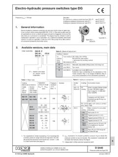
7 +80 C, Note the viscosity range !Permissible temperature during start: -40 C (observe start-viscosity!), as long as the service tempera-ture is at least 20K higher for the following degradable Pressure fluids: Observe manufacturer's specifications. By consideration of thecompatibility with seal material not over +70 characteristic dataAdjustability during serviceOnly tool adjustable vers.!D 7745 page 4|p - Q -curve P Aor A PAttention:Obey the note in "Direction of flow"(page 3) Pressure at the outlet pA(bar)Back Pressure |p (bar)Flow QA(lpm) pA- QP A- curvesThe set Pressure applies to flowQP A 0 lpm. With flow Q > 0, consumer is moving, the pres-sure on the secondary side pAwilldrop slightly. This effect can be usually neglected during :A Pressure gauge should beused whenever the pressuresetting is adjusted or altered!Flow QA(lpm) CurvesPressure specificationThe Pressure setting pAwill be set in the factory with pP, alternationsThe actual Pressure pAbeing received will vary slightly as it directly depends on the Pressure at the primary side pPdue to a internal design based typePressure range-08-1 -2-5-081-11-21-51 CDK 3* bar* bar* bar* barCDK 32* bar* bar* bar* barCDK 35* bar* bar* bar* barPressure change|pA(bar) at pp*10 barFurther characteristic dataType -1/4= kg-1 kg-1/4 S(SR)= kg-P= kg-SP= kg Mass (weight)Basic type (cartridge valve )Type kgCombination with connection block:D 7745 page dimensionsAll dimensions are in mm and are subject to change without notice!
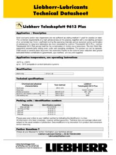
8 Type (cartridge valve )Type CDK 3, CDK 32 and CDK 35 valve bodies a/f 24 Torque 70(90) Nm 3)Provision for lead sealSealing nut hole a/f 30 Torque 60(80) Nm 3)O-ring ( ) 3)AU 90 ShSealing edgeTool adjustableTravelstopKANTSEALDKAR00021-N9 0 NBR 90 hole(For tapped plug, see page 7)1) If Pressure at A exceeds 100 bar a counter bore isrequired to allow proper sealing!2) Thread counter bore max. #24+ ) Klammerwerte f r CDK (-081) Pressure adjustment(guidline)Attention:Any Pressure re-adjustment should be monitored with a Pressure gauge!Coding|p/revolution(bar/rev)083712 5216510 Assembly notesValve bodies <a/f 24 Torque 70(90) Nm 3)Locking =Manifold;Before screwing the valve body into the manifold slacken the counter /sealing nut until the travel stop.<Screw in the valve body (a/f 24) and tighten with the correct metallic sealing of the inlet to the outlet takes place at the contactarea of the facial sealing edge and the stepped shoulder of the corediameter at the location the counter/sealing nut (a/f 30) with the correct stop ;Counter/sealing nut (a/f 30)Torque 60(80) Nm 3)Sealing edge <<Coding|p/revolution (bar/rev)08146113121205112 Manually adjustablelockable; one key is scopeof deliveryValve bodiesa/f 24 Torque 70(90) Nm 3) valve bodiesa/f 27 Torque 70(90) Nm 3)D 7745 page with connection block for pipe connectionType CDK 3(32, 35).
9 - 1/4 and CDK 3(32, 35) - .. - 1/4 - switch typeDG acc. to D 5440 Basic type (cartridgevalve )Basic type (cartridgevalve )# thru-hole# acc. to ISO 228/1 (BSPP): A, P, R and M = G 1/4 Ports acc. to ISO 228/1 (BSPP): A, P, and R = G 1/4 Pressure adjustment Pressure limiting valvePressure range (bar/rev)|p/revolution (bar/rev).. Pressure adjustment of the Pressure reducingvalve, see sect. !Sealing via O-rings NBR 90 Sh(The hole pattern is equal to type ADM 11 P acc. to D 7120. The O-ring-cavety exists for drain line R (or L). Here only needed with type ). Pressure limitingvalveHole pattern ofthe manifold(top view)M6, 12 deepType CDK 3(32, 35) - .. - 1/4 S(SR) with connection block for manifold mountingType CDK 3(32, 35) - .. - PType CDK 3(32, 35) - .. - SPWithout DG (but may beretrofittedhere) Pressure limitingvalveTool adjustableManually adjustableD 7745 page for useAlternations of Pressure may occur due to lack of leakage in closed state (idle position) if used in circuits where the Pressure is main-tained over a long period without switching operations clamping of work piece pallets.
10 The Pressure will rise if the temperaturerises ( radiation of the sun) or additional load is induced, Pressure drops if the temperature drops (stand-still over night) or theload is reduced and the pump is switched off. These effects will be more pronounced with short and rigid piping. Hoses or additional volume ( accumulators type AC 13 acc. to D 7571) will minimize these Pressure effects described above are caused by the ratio of temperature induced expandation and compression coefficient (theoretical1:10, |}= 1K = |p,10bar). A ratio of approx. 1:1 is realistic due to the flexibility of piping and tubing (backed by experience).Ports acc. to ISO 228/1 (BSPP): A, P, and R = G 1/4 Sealing via O-ring NBR 90 ShAdapter plate (connectionblock for pipeconnection)Type CDK 3(32, 35) - .. - SP - ../.. - 1/4(Type CDK 3(32, 35) - .. - P - ../.. - 1/4 analogous)For missing dimensions see page 6 below!