Transcription of 35 PLASTIC ANALYSIS
1 PLASTIC ANALYSIS Version II 35 - 1 PLASTIC ANALYSIS INTRODUCTION The elastic design method, also termed as allowable stress method (or Working stress method), is a conventional method of design based on the elastic properties of steel. This method of design limits the structural usefulness of the material upto a certain allowable stress, which is well below the elastic limit. The stresses due to working loads do not exceed the specified allowable stresses, which are obtained by applying an adequate factor of safety to the yield stress of steel. The elastic design does not take into account the strength of the material beyond the elastic stress. Therefore the structure designed according to this method will be heavier than that designed by PLASTIC methods, but in many cases, elastic design will also require less stability bracing. In the method of PLASTIC design of a structure, the ultimate load rather than the yield stress is regarded as the design criterion.
2 The term PLASTIC has occurred due to the fact that the ultimate load is found from the strength of steel in the PLASTIC range. This method is also known as method of load factor design or ultimate load design. The strength of steel beyond the yield stress is fully utilised in this method. This method is rapid and provides a rational approach for the ANALYSIS of the structure. This method also provides striking economy as regards the weight of steel since the sections designed by this method are smaller in size than those designed by the method of elastic design. PLASTIC design method has its main application in the ANALYSIS and design of statically indeterminate framed structures. BASIS OF PLASTIC THEORY Ductility of Steel Structural steel is characterised by its capacity to withstand considerable deformation beyond first yield, without fracture. During the process of 'yielding' the steel deforms under a constant and uniform stress known as 'yield stress'.
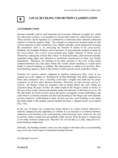
3 This property of steel, known as ductility, is utilised in PLASTIC design methods. Fig. 1 shows the idealised stress-strain relationship for structural mild steel when it is subjected to direct tension. Elastic straining of the material is represented by line OA. AB represents yielding of the material when the stress remains constant, and is equal to the yield stress, fy. The strain occurring in the material during yielding remains after the load has been removed and is called the PLASTIC strain and this strain is at least ten times as large as the elastic strain, Hy at yield point. Copyright reserved 35 PLASTIC ANALYSIS Version II 35 - 2 When subjected to compression, the stress-strain characteristics of various grades of structural steel are largely similar to Fig. 1 and display the same property of yield. The major difference is in the strain hardening range where there is no drop in stress after a peak value.
4 This characteristic is known as ductility of steel. Theoretical Basis As an incremental load is applied to a beam, the cross-section with greatest bending moment will eventually reach the yield moment. Elsewhere the structure is elastic and the 'peak' moment values are less than yield. As load is incremented, a zone of yielding develops at the first critical section, but due to ductility of steel, the moment at that section remains about constant. The structure, therefore, calls upon its less heavily stressed portions to carry the increase in load. Eventually the zones of yielding are formed at other sections until the moment capacity has been exhausted at all necessary critical sections. After reaching the maximum load value, the structure would simply deform at constant load. Thus it is a design based upon the ultimate load-carrying capacity (maximum strength) of the structure.
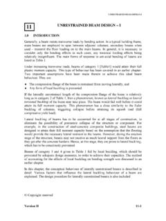
5 This ultimate load is computed from a knowledge of the strength of steel in the PLASTIC range and hence the name ' PLASTIC '. Perfectly PLASTIC Materials The stress-strain curve for a perfectly PLASTIC material upto strain hardening is shown in Fig. 2. Perfectly PLASTIC materials follow Hook's law upto the limit of proportionality. The slopes of stress-strain diagrams in compression and tension the values of Young's modulus of elasticity of the material , are equal. Also the values of yield stresses in tension and compression are equal. The strains upto the strain hardening in tension and compression are also equal. The stress strain curves show horizontal plateau both in tension and compression. Such materials are known as perfectly PLASTIC materials. fy A B Stress f O Strain H Fig. 1 Idealised stress strain curve for steel in tension Strain hardening commences Strain hardening PLASTIC ANALYSIS Version II 35 - 3 Fully PLASTIC Moment of a Section The fully PLASTIC moment Mp, of a section is defined as the maximum moment of resistance of a fully plasticized or yielded cross-section.
6 The assumptions used for finding the PLASTIC moment of a section are: (i) The material obeys Hooke's law until the stress reaches the upper yield value; on further straining, the stress drops to the lower yield value and thereafter remains constant. (ii) The yield stresses and the modulus of elasticity have the same value in compression as in tension. (iii) The material is homogeneous and isotropic in both the elastic and PLASTIC states. (iv) The plane transverse sections (the sections perpendicular to the longitudinal axis of the beam) remain plane and normal to the longitudinal axis after bending, the effect of shear being neglected. (v) There is no resultant axial force on the beam. (vi) The cross section of the beam is symmetrical about an axis through its centroid parallel to plane of bending. (vii) Every layer of the material is free to expand and contract longitudinally and laterally under the stress as if separated from the other layers.
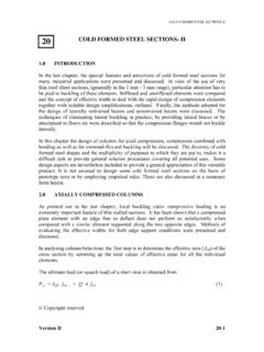
7 STRESS STRAIN COMPRESSION TENSION fy fy Fig. 2 Stress - Strain Curve for perfectly PLASTIC materials PLASTIC ANALYSIS Version II 35 - 4In order to find out the fully PLASTIC moment of a yielded section of a beam as shown in Fig. 3, we employ the force equilibrium equation, namely the total force in compression and the total force in tension over that section are equal. Total compression , C = Total tension , T fy . A1 = fy. A2 ? A1 = A2 A = A1 + A2 A1 = A2 = A/2 PLASTIC Moment of resistance, (1) where Zp , the PLASTIC modulus of the section = The PLASTIC modulus of a completely yielded section is defined as the combined statical moment of the cross-sectional areas above and below the neutral axis or equal area axis.
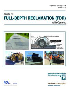
8 It is the resisting modulus of a completely plasticised section. BENDING OF BEAMS SYMMETRICAL ABOUT BOTH AXES The bending of a symmetrical beam subjected to a gradually increasing moment is considered first. The fibres of the beam across the cross section are stressed in tension or compression according to their position relative to the neutral axis and are strained in accordance with Fig. 1. pyyyypZfyy2 AfyAfyAfM 212211 21yy2A Fig. 3 C = fy .A1 T = fy . A2 fy fy 1y2yA2 G2 A1 G1 PLASTIC ANALYSIS Version II 35 - 5 While the beam remains entirely elastic the stress in every fibre is proportional to its strain and to its distance from the neutral axis. The stress (f) in the extreme fibres cannot exceed fy. (see Fig. 4) When the beam is subjected to a moment slightly greater than that, which first produces yield in the extreme fibres, it does not fail. Instead the outer fibres yield at constant stress (fy) while the fibres nearer to the neutral axis sustain increased elastic stresses.
9 Fig. 5 shows the stress distribution for beams subjected to such moments. Such beams are said to be 'partially PLASTIC ' and those portions of their cross-sections, which have reached the yield stress, are described as ' PLASTIC zones'. Fig. 4 Elastic stresses in beams Neutral Axis f f d fy f Fig. 5 Stresses in partially PLASTIC beams PLASTIC Zone (Compression) PLASTIC Zone (Tension) Neutral Axis (a) Rectangular section (b) I - section (c) Stress distribution for (a) or (b) fy fy PLASTIC ANALYSIS Version II 35 - 6 The depths of the PLASTIC zones depend upon the magnitude of the applied moment. As the moment is increased, the PLASTIC zones increase in depth, and, it is assumed that PLASTIC yielding can occur at yield stress (fy) resulting in two stress blocks, one zone yielding in tension and one in compression. Fig. 6 represents the stress distribution in beams stressed to this stage.
10 The PLASTIC zones occupy the whole of the cross section, and are described as being 'fully PLASTIC '. When the cross section of a member is fully PLASTIC under a bending moment, any attempt to increase this moment will cause the member to act as if hinged at the neutral axis. This is referred to as a PLASTIC hinge. The bending moment producing a PLASTIC hinge is called the full PLASTIC moment and is denoted by 'Mp'. Note that a PLASTIC hinge carries a constant moment, MP. GENERAL REQUIREMENTS FOR UTILISING PLASTIC DESIGN CONCEPTS Generally codes (such as IS 800, BS 5950) allow the use of PLASTIC design only where loading is predominantly static and fatigue is not a design criterion. For example, in order to allow this high level of strain, BS 5950 prescribes the following restrictions on the properties of the stress-strain curve for steels used in plastically designed structures (clause ).