Transcription of 35127 OWNER’S MANUAL AND INSTALLATION GUIDE
1 ABCDEFGHIJKLEM*NHardware Kit(s)Long Par tsCarton Roll-upCarton Roll-upShort Par ts& Vinyl Sweep(In roll-up) Pencil Tape measure Utility knife or scissors Centerpunch Phillips Screwdriver Flat Blade Screwdriver Pliers Hammer Hack saw Drill 3/32" drill bit 1/8" drill bit Sawhorses (Optional) Power Screwdriver (Optional) 1/16" to 3/16" shims (as required) 1 owner S MANUAL AND INSTALLATION GUIDEP ella Extruded Rolscreen Storm DoorsNote To The Installer: This owner s MANUAL is the property of the homeowner.
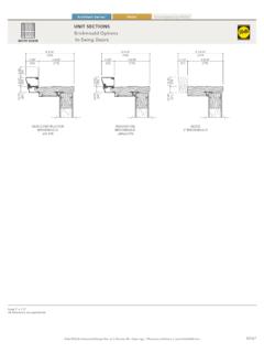
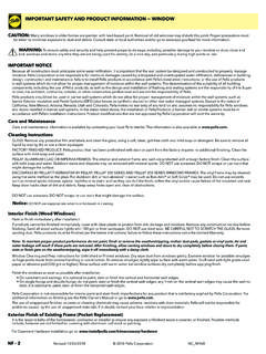
2 Please leave it with the homeowner upon completion of the Number: 35127 Door ComponentsA. Door PanelB. Hinge Mounting FrameC. Latch Mounting FrameD. Top Mounting FrameE. Vertical Screw CoverF. Horizontal Screw CoverG. Bottom ExpanderH. Sweep (Black Vinyl) (Some models have two)I. Glass Panel BottomJ. Glass Panel TopK. RolscreenL. Hadware Kit - Closers and INSTALLATION screwsM. Handle Kit* (Some models have one combined kit)N. INSTALLATION GuideIMPORTANT: Before discarding the carton, make sureALL parts are accounted for.
3 Check the carton roll-upsat the top and SHOOTING GUIDE : Located on back side of this manualTools RequiredInstallation will require two or more persons for safety order replacement parts, call1-800-374-4758 or visit us at have your registrationand model number ready whenyou contact us either bytelephone or on the TO USE APPROPRIATE PERSONAL PROTECTIVE Number:Door Model Number:(see carton lablel)Left HingeDoorsRight HingeDoorsEntry Door1 AYour entryway opening width (measured in inches)30 Storm Doorless than 29-7/8 29-7/8 to 30-1/16 Over 30-1/16 to 30-3/8 More than 30-3/8 32 Storm Doorless than 31-7/8 31-7/8 to 32-1/16 Over 32-1/16 to 32-3/8 More than 32-3/8 34 Storm Doorless than 33-7/8 33-7/8 to 34-1/16 Over 34-1/16 to 34-3/8 More than 34-3/8 36 Storm Doorless than 35-7/8 35-7/8 to 36-1/16 Over 36-1/16 to 36-3/8 More than 36-3/8 Shim RequirementCustom door sizerecommendedNo shim requiredAdd shims on the hinge side to get down to the No shim required width
4 RangeCustom door sizerecommendedShimShimShim must not extend beyond entrywayHinge1"2 BEFORE YOU BEGINA. Remove the door from the : Before discarding the carton, make sure ALL parts are accounted for. Check the carton roll-ups at the top and Record the door s registration number for future reference . Note: The door s registration label is located on the hinge mounting Determine which side you want your storm door to hinge when viewed from the exterior of your home. 1 ENTRYWAY OPENING PREPARATION A.
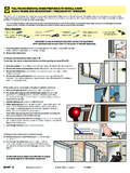
5 Verify the door will fit in the entryway opening. Measure the width of the opening in three locations. Using the smallest measurement, refer to the chart for shimming requirements and shim If required, shim the entry door frame. Using four shim sections each about 8 to 12 long, position to align with the hinges on the storm door. DO NOT extend the shim beyond the face of the facing up3 CLeft Hinge DoorsRight Hinge DoorsTop End3/32" OverhangScore LineWeatherstripping3A3 BHingeScrewWeatherstrippingHingeScrewOut erHoleScore LinePre-drilledHoleTop End3/32" Overhang3A3 BInside facing up3D3 DOuterHolePre-drilledHoleL1L23F32 GLASS AND SCREEN A.
6 The glass and screen should be left in place while installing the storm door. The shipping block(s) at the top of the sash should not be removed until the INSTALLATION is HINGE MOUNTING FRAME ASSEMBLY A. With the interior of the door facing up, position the hinge mounting frame on the door panel. Note: Notice the location of the weather-stripping. B. Align the pre-drilled hole with the outer hinge hole and install one hinge screw (#8 x 3/4" hex head). C. Check to ensure there is a 3/32" overhang from the highest point of the top of the door.
7 Note: If the hinge side mounting frame extends more than or less than 3/32" above the top of the door panel, remove the hinge screw. Position the hinge side mounting frame to achieve the 3/32" overhang, and centerpunch and drill a new 1/8" diameter hole through one of the other hinge holes. Install the (#8 x 3/4" hex head) hinge screw in the new hole. D. Align the hinge holes with the score line on the storm door. E. Centerpunch and drill the remaining hinge holes using a 1/8" drill bit and install the remaining hinge screws.
8 F. Determine the finished length of the mounting frame. Measure the entryway height in two locations (see L1 and L2) on the side where the storm door hinges will be located and subtract 1/8" from both dimensions. Note: Measure the entryway with brickmould at the point where the brickmould attaches to the entry door llielgnAL1L2 StraightCutAngleCutL1 IroiretnEroiretxIroiretn3G4B4 AedilS4 CInterior Side4 DBlackVinylSweep1/2 ROIRETXE edilS4E43 HINGE MOUNTING FRAME ASSEMBLY (CONTINUED) G.
9 Turn the door over so the exterior faces up. Starting at the top of the hinge mounting frame and working toward the bottom, measure and mark the lengths L1 and L2 taken from the previous step. H. Matching the angle of your entryway sill, cut the bottom of the hinge mounting frame to length. Note: For a simplified INSTALLATION , a straight cut a L1 may be made. For a more professional looking INSTALLATION , an angled cut from L1 to L2 may be BOTTOM EXPANDER ASSEMBLY A.
10 Slide the black vinyl sweep along the full length of the bottom expander. Note: Some models have two sweeps. B. Lock the sweep in place by pinching the ends of the inner legs. C. Cut the excess sweep from each end. D. For models with two sweeps, cut away a 1/2" wide notch from both ends of the interior sweep. E. Place the bottom expander onto the bottom of the door with the sweep toward the interior. DO NOT install screws in the bottom expander at this time, adjustments are made in a later Mounting Frame5A5B5 CSlide Against Jamb BrickmouldMounting Frame Screw $Inside JambScrewTop Mounting Frame6 CMounting Frame Screw7AL3L4S llielgnAAngleCut7BL3 Weather StrippingRightHandLeftHandL4 StraightCut5 Two or more persons may be required for the following INSTALL THE DOOR Note: The illustrations show the INSTALLATION of a left hinge door.