Transcription of 4PIN SSOP PHOTOTRANSISTOR cosmo …
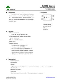
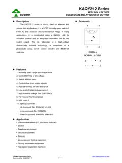
1 cosmo Electronics Corp. Document No. - 1 - cosmo kps2801 Series4 PIN ssop PHOTOTRANSISTORPHOTOCOUPLERz Description The kps2801 series is DC-input single channel which contains a light emitting diode optically coupled to a PHOTOTRANSISTOR . It is packaged in a 4-pin ssop package. The input-output isolation voltage is rated at 3750 Vrms. z Schematic 1. Anode 2. Cathode 3. Emitter 4. Collector z Features 1. Pb free and RoHS compliant 2. High isolation voltage (VISO=3750 Vrms) 3. Small and thin package( 4pin ssop , pin pitch ) 4. High collector to emitter voltage(VCEO=80V) 5. High-speed switching tr =3 s (typ.), tf =5 s (typ.) 6. MSL class 1 7. Agency Approvals: UL Approved (No. E169586): UL1577 c-UL Approved (No. E169586) VDE Approved (No. 40010469): DIN EN60747-5-5 FIMKO Approved: EN60065, EN60950 SEMKO Approved: EN60065, EN60950 CQC Approved: GB8898-2011, z Applications Programmable logic controllers Measuring instruments Power supply Hybrid IC 2314 cosmo Electronics Corp.
2 Document No. - 2 - cosmo kps2801 Series4 PIN ssop PHOTOTRANSISTORPHOTOCOUPLERz Outside Dimension Unit : mm TOLERANCE : z Device Marking Notes: 2801 YWW Y: Year code / WW: Week code cosmo Electronics Corp. Document No. - 3 - cosmo kps2801 Series4 PIN ssop PHOTOTRANSISTORPHOTOCOUPLERz Absolute Maximum Ratings (Ta=25 C) Parameter Symbol Rating Unit Input Forward current IF 50 mA Peak forward current(*1) IFP 1 A Reverse voltage VR 6 V Power dissipation PD 60 mW Power dissipation derating PD/ C mW/ C Output Collector-Emitter voltage VCEO 80 V Emitter-Collector voltage VECO 6 V Collector current IC 50 mA Collector power dissipation PC 160
3 MW Collector power dissipation derating PC/ C mW/ C Isolation voltage 1 minute(*2) Viso 3750 Vrms Operating temperature Topr -55 to +115 C Storage temperature Tstg -55 to +125 C *1 PW=100 s,Duty Cycle=1%. *2 AC voltage for 1minute at T =25 , C RH=60% between input and output. z Electro-optical Characteristics (Ta=25 C) Parameter SymbolConditions Min. Typ. Max. UnitInput Forward voltage VF IF=5mA Reverse current IR VR=5V 5 ATerminal capacitance Ct V=0, f=1 MHZ 60 pFOutput Collector dark current ICEO VCE=80V,IF=0mA 100nATransfer charac- teristics Current transfer ratio CTR IF=5mA, VCE=5V 50 600%IF=1mA, VCE=5V 15 - - %Collector-Emitter saturation voltage VCE(sat) IF=10mA, Ic=2mA Isolation resistance Riso DC500V 5x10¹⁰ 1011 Floating capacitance Cf V=0, f=1 MHZ - pFResponse time (Rise)(*3) tr Vce=5V,Ic=2mA,RL=100 3 18 sResponse time (Fall) (*3) tf 5 18 s*3 Test Circuit for Switching Time cosmo Electronics Corp.
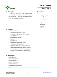
4 Document No. - 4 - cosmo kps2801 Series4 PIN ssop PHOTOTRANSISTORPHOTOCOUPLERC lassification table of current transfer ratio is shown below. CTR Rank. CTR ( % ) KPS28010A 80 TO 160 KPS28010B 130 TO 260 KPS28010C 200 TO 400 KPS28010D 300 TO 600 KPS28010E 50 TO 600 Transfer Ratio vs. Forward Current Current Transfer Ratio CTR ( % ) 1252050050100150200250300350400450500Ta= 25 C010V = Forward Current IF (mA) Collector Power Dissipation vs.
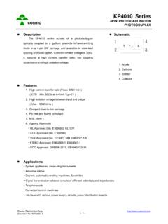
5 Ambient Temperature Dark Current vs. Ambient Temperature Collector Power Dissipation PC ( mW ) 1252502007550251501005000-55115 Collector Dark Current ICEO ( A ) 115755025-5-6-71010-8-9101010-100-5510-1 110 Vce=80V Ambient Temperature Ta ( C) Ambient Temperature Ta ( C) Forward Current vs. Ambient Temperature Current vs. Forward Voltage Forward Current IF ( mA ) 6010-550200253040505075115 125 Forward Current IF ( mA ) Ta=75 50 -25 0 25 CCCCC500200100502010 Ambient Temperature Ta ( C) Forward Voltage VF (V) cosmo Electronics Corp. Document No. - 5 - cosmo kps2801 Series4 PIN ssop Collector Current vs. Collector-Emitter Voltage Current Transfer Ratio vs. Ambient Temperature Collector Current IC (mA) Ta=25 8210051015765435mA10mAI = 30mA252030F20mA9C Relative Current Transfer Ratio ( % ) -550-2550255011575I =5m AVce=5V1501000F Collector-Emitter Voltage VCE (V) Ambient Temperature Ta ( C) Collector-Emitter Saturation Voltage vs.
6 Ambient Temperature Collector-Emitter Saturation Voltage vs. Forward Current Collector-Emitter Saturation Voltage VCE ( V ) I = A100115 Collector-Emitter Saturation Voltage VCE ( V ) Ic=1mA00512345610Ic=7mAIc=5m AIc=3mATa=25 Ic= AC7 Ambient Temperature Ta ( C) Forward Current IF (mA) Response Time (Rise) vs. Load Resistance Response Time (Fall) vs. Load Resistance Response Rise Time ( us ) 1 2 5 10trTa=25 20 50100 Vce=5 VIc= 2m A10C Response Fall Time ( us ) = 2 m ATa=25 1 2 5 10 20100 50 Load Resistance RL (K ) Load Resistance RL (K ) cosmo Electronics Corp. Document No. - 6 - cosmo kps2801 Series4 PIN ssop PHOTOTRANSISTORPHOTOCOUPLERz Test Circuit for Response Time Vcetrtf90%10%2134 RVccVceIFIFL cosmo Electronics Corp. Document No. - 7 - cosmo kps2801 Series4 PIN ssop PHOTOTRANSISTORPHOTOCOUPLERz Recommended Soldering Conditions (a) Infrared reflow soldering Peak reflow soldering Time of peak reflow temperature Time of temperature higher than 230 C Time to preheat temperature from 180~190 C Time(s) of reflow Flux 260 C or below (package surface temperature) 10 sec 30-60 sec 60-120 sec Two Rosin flux containing small amount of chlorine (The flux with a maximum chlorine content of Wt% is recommended.)
7 Recommended Temperature Profile of Infrared Reflow 180 C190 C230 C260 C60-120 sec30-60 sect (s)temperature10 sec M ax. (b) Wave soldering Temperature Time Preheating conditions Time(s) of reflow Flux 260 C or below (molten solder temperature) 10 seconds or less 120 C or below (package surface temperature) One Rosin flux containing small amount of chlorine (The flux with a maximumchlorine content of Wt% is recommended.) (c) Cautions Fluxes Avoid removing the residual flux with freon-based and chlorine-based cleaning solvent. Avoid shorting between portion of frame and leads. cosmo Electronics Corp. Document No. - 8 - cosmo kps2801 Series4 PIN ssop PHOTOTRANSISTORPHOTOCOUPLERz Numbering System kps2801 Y (Z) Notes: kps2801 = Part No. Y = CTR rank option (A ~ E) Z = Tape and reel option (TLD TRU) Option Description Packing quantity TLD TLD tape & reel option 3000 units per reel TRU TRU tape & reel option 3000 units per reel z Recommended Pad Layout for Surface Mount Lead Form Unit :mm cosmo Electronics Corp.
8 Document No. - 9 - cosmo kps2801 Series4 PIN ssop PHOTOTRANSISTORPHOTOCOUPLERz 4-pin ssop Carrier Tape & Reel TOLERANCE cosmo Electronics Corp. Document No. - 10 - cosmo kps2801 Series4 PIN ssop PHOTOTRANSISTORPHOTOCOUPLERz Application Notice The statements regarding the suitability of products for certain types of applications are based on cosmo 's knowledge of general applications of cosmo products. Such statements are not binding statements about the suitability of products for a particular application. It is the customer's responsibility to verify the specifications are suitable for use in a particular application. Customers are solely responsible for all aspects of their own product design or applications. The parameters provided in the datasheet may vary in different applications and performance may vary over time. All operating parameters (including typical parameters) must be validated by customer's technical experts for different applications.
9 cosmo assumes no liability for customer product design or applications. Product specifications do not expand or otherwise change cosmo 's terms and conditions of purchase, including but not limited to the warranty expressed therein. When using cosmo products, please comply with safety standards and instructions. cosmo has no liability and responsibility to the damage caused by improper use of the instructions specified in the specifications. cosmo products are designed for use in general electronic equipment such as telecommunications, office automation equipments, personal computers, test and measurement equipments, consumer electronics, industrial control, instrumentation, audio, video. cosmo devices shall not be used in equipment that requires higher level of reliability and safety, such as nuclear power control equipment, telecommunication equipment(trunk lines), space application, medical and other life supporting equipments, and equipment for aircraft, military, automotive or any other application that can cause human injury or death.
10 cosmo reserves the right to change the specifications, data, characteristics, structure, materials and other contents at any time without notice. Please contact cosmo to obtain the latest specification. cosmo disclaim any and all liability for any errors, inaccuracies or incompleteness contained in any datasheet or in any other disclosure relating to any product.