Transcription of 5.1 Shell-and-Tube Heat Exchangers - Homepages at WMU
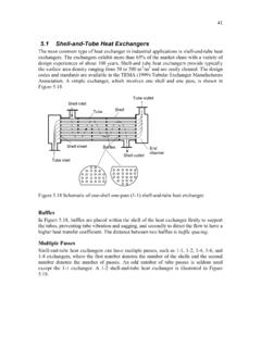
1 41. Shell-and-Tube heat Exchangers The most common type of heat exchanger in industrial applications is Shell-and-Tube heat Exchangers . The Exchangers exhibit more than 65% of the market share with a variety of design experiences of about 100 years. Shell- and tube heat Exchangers provide typically the surface area density ranging from 50 to 500 m2/m3 and are easily cleaned. The design codes and standards are available in the TEMA (1999)-Tubular exchanger Manufacturers Association. A simple exchanger , which involves one shell and one pass, is shown in Figure Tube outlet Shell inlet Shell Tube Shell sheet Baffles End channel Shell outlet Tube inlet Figure Schematic of one-shell one-pass (1-1) Shell-and-Tube heat exchanger .
2 Baffles In Figure , baffles are placed within the shell of the heat exchanger firstly to support the tubes , preventing tube vibration and sagging, and secondly to direct the flow to have a higher heat transfer coefficient. The distance between two baffles is baffle spacing. Multiple Passes Shell-and-Tube heat Exchangers can have multiple passes, such as 1-1, 1-2, 1-4, 1-6, and 1-8 Exchangers , where the first number denotes the number of the shells and the second number denotes the number of passes. An odd number of tube passes is seldom used except the 1-1 exchanger .
3 A 1-2 Shell-and-Tube heat exchanger is illustrated in Figure 42. Tube outlet Shell inlet End Shell channel Tube Pass partition Baffles Shell outlet Tube inlet Figure Schematic of one-shell two-pass (1-2) Shell-and-Tube heat exchanger . Lt B. Ds Figure Dimensions of 1-1 Shell-and-Tube heat exchanger Dimensions of Shell-and-Tube heat exchanger Some of the following dimensions are pictured in Figure L = tube length N t = number of tube N p = number of pass Ds = Shell inside diameter N b = number of baffle B = baffle spacing The baffle spacing is obtained Lt B= ( ).
4 Nb +1. 43. Shell-Side Tube Layout Figure shows a cross section of both a square and triangular pitch layouts. The tube pitch Pt and the clearance Ct between adjacent tubes are both defined. Equation ( ) of the equivalent diameter is rewritten here for convenience 4 Ac De = ( ). Pheated From Figure , the equivalent diameter for the square pitch layout is De =. (. 4 Pt d o 4. 2 2. ) ( ). d o From Figure , the equivalent diameter for the triangular pitch layout is 3Pt 2 d o 2 . 4 .. 4 8. De = ( ). d o 2. The cross flow area of the shell Ac is defined as Ds C t B.
5 Ac = ( ). PT. do do di di Flow Ct Pt Ct Pt (a) (b). Figure (a) Square-pitch layout, (b) triangular-pitch layout. The diameter ratio dr is defined by do dr = ( ). di Some diameter ratios for nominal pipe sizes are illustrated in Table in Appendix C. The tube pitch ratio Pr is defined by 44. Pt Pr = ( ). do The tube clearance Ct is obtained from Figure Ct = Pt d o ( ). The number of tube Nt can be predicted in fair approximation with the shell inside diameter Ds. Ds2 4. N t = (CTP ) ( ). ShadeArea where CTP is the tube count constant that accounts for the incomplete coverage of the shell diameter by the tubes , due to necessary clearance between the shell and the outer tube circle and tube omissions due to tube pass lanes for multiple pass design [1].
6 CTP = for one-pass exchanger CTP = for two-pass exchanger ( ). CTP = for three-pass exchanger ShadeArea = CL Pt 2 ( ). where CL is the tube layout constant. CL = 1 for square-pitch layout ( ). CL = sin(60 ) = for triangular-pitch layout Plugging Equation ( ) into ( ) gives CTP Ds2. CTP Ds2. Nt = 2 = ( ). 4 CL Pt 4 CL Pr2 d o2. Table Summary of Shell-and-Tube heat Exchangers Description Equation q = m& 1c p1 (T1i T1o ) ( ). q = m& 2 c p 2 (T2o T2i ). Basic Equations ( ). heat transfer areas of the Ai = d i N t L ( ).
7 Inner and outer surfaces Ao = d o N t L ( ). of an inner pipe 45. 1 Ao Overall heat Transfer Uo =. d . Coefficient ln o ( ). d + i +. 1 1. hi Ai 2 kL ho Ao Tube side u m d i m& d i Reynolds number Re D = = ( ). Ac . d i2 N t ( ). Ac =. 4 Np 1 hd d Re Pr 3 . Laminar flow Nu D = i = i ( ). (Re < 2300) kf L s . < Pr < 16,700. < ( s ) < Use Nu D = if Nu D < Nu D =. hd i =. ( f / 2)(Re D 1000) Pr Turbulent flow (Re > 2300). kf 12. (. 1 + ( f / 2 ) Pr 2 3 1 ) ( ). 3000 < Re D < 5 10 6 [4]. Pr 2000. f = ( ln (Re D ) ).
8 2. Friction factor ( ). Shell side Square pitch layout (Figure ) De =. (. 4 Pt d o 4. 2 2. ) ( ). d o Triangular pitch layout 3Pt 2 d o 2 . (Figure ) 4 . ( ). 4 8. De = . d o 2. Cross flow area DCB ( ). Ac = s t Pt u D m& De Reynolds number Re D = m e = ( ). Ac . 46. h D . Nusselt number Nu = o e = Re Pr 1 3 ( ). kf s . 6. 2000 <Re < 1 x 10. -NTU Method heat transfer unit U o Ao ( ). NTU =. (NTU) (m& c p )min (m& c ). p min Cr =. Capacity ratio (m& c ). p max ( ).. ( ) 12 [ ( ) ] . 1 + exp NTU 1 1 + C r2. 12.
9 1 exp[ NTU (1 + C ) ] ( ). Effectiveness = 2 1 + C r + 1 + C r 2. 2 12. One shell (2, 4,.. passes) 1 r NTU 1 = NTU N p heat transfer unit (NTU) (. NTU = 1 + C r ) E 1 . 2 1 2. ln ( ). E +1 . 2 (1 + C r ). where E =. (1 + C ) r 2 12. =. q =. (m& c )(T T ) = (m& c )(T. 1 p1 1i 1o 2 p2 2o T2i ). Effectiveness qmax (m& c ) (T T ) (m& c ) (T. p min 1i 2i p min 1i T2i ) ( ). heat transfer rate q = (m& c p )min (T1i T2i ) ( ). Tube Side Pressure Drop f Lt 1. Pressure drop P = 4 + 1 N p v 2 ( ). di 2. Laminar flow f = 16 Re D ( ).
10 F = ( ln (Re D ) ). Turbulent flow 2 ( ). Shell Side Pressure Drop 47. Ds ( ). P = f (N b + 1) 1 v 2. De 2. ( ). f = exp( ln (Re s )). 48. Example Miniature Shell-and-Tube heat exchanger A miniature Shell-and-Tube heat exchanger is designed to cool engine oil in an engine with the engine coolant (50% ethylene glycol). The engine oil at a flow rate of kg/s enters the exchanger at 120 C and leaves at 115 C. The 50% ethylene glycol at a rate of kg/s enters at 90 C. The tube material is Cr alloy (kw = W/mK). Fouling factors of m2K/W for engine oil and m2K/W for 50% ethylene glycol are specified.