Transcription of 5-Port Power over Ethernet Managed Switch
1 5-Port Power over Ethernet Managed SwitchModel: TS-5-POEI ntroductionThank you for purchasing the Ubiquiti Networks TOUGHS witch PoE. This Quick Start Guide is designed to guide you through installation and includes warranty ContentsTOUGHS witch PoEScrews ( , Qty. 2)Anchors ( , Qty. 2) 5-Port Power over Ethernet Managed SwitchModel: TS-5-POEP ower Adapter (24V, ) Power CordQuick Start GuideTERMS OF USE: All Ethernet cabling runs must use CAT5 (or above). Shielded Ethernet cable and earth grounding must be used for outdoor installations as conditions of product warranty. TOUGHC able is designed for outdoor installations. It is the customer s responsibility to follow local country regulations, including operation within legal frequency channels, output Power , and Dynamic Frequency Selection (DFS) OverviewBack PanelPowerGrounding SlotGrounding SlotVentilation HolesNote: There are additional ventilation holes on the top and sides of the Panel PortsManagementUSBR eset1-5 InterfaceDescriptionManagement10/100 Mbps port used to access the TOUGHS witch Configuration Interface.
2 USBR eserved for future 1-510/100/1000 Mbps ports for switching and PoE (also available for management by default).ResetTo reset to factory defaults, press and hold the Reset button for more than 10 seconds while the unit is already powered Panel LEDsPower/LinkPoESpeed/Link/ActLEDS tateStatusManagementPower/LinkOffNo Power /No LinkAmberAfter bootup, the LED indicates Power . After an initial link is established, the LED indicates a 10/100 Mbps connection. If the link terminates, the LED turns off until a link is re-established. If the unit reboots, the LED will again indicate Power until a link is 1-5 PoEOffNo Power over EthernetGreen24V Power over EthernetSpeed/Link/ActOffNo linkAmberLink established at 10/100 MbpsAmber FlashingLink activity at 10/100 MbpsGreenLink established at 1000 MbpsGreen FlashingLink activity at 1000 MbpsHardware InstallationPlace the TOUGHS witch on a bench top or other flat : FAILURE TO PROVIDE PROPER VENTILATION MAY CAUSE FIRE HAZARD.
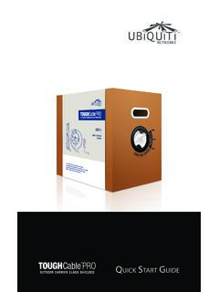
3 KEEP AT LEAST 20 MM OF CLEARANCE NEXT TO THE VENTILATION HOLES FOR ADEQUATE AIRFLOW. Installation Requirements Drill, 6 mm drill bit, and Phillips screwdriver (wall-mounting) For outdoor applications, shielded Category 5 (or above) cabling should be used for all wired Ethernet connections and should be grounded through the AC ground of the Power supply. We recommend that you protect your networks from harmful outdoor environments and destructive ESD events with industrial-grade, shielded Ethernet cable from Ubiquiti Networks. For more details, visit Important: Although the cabling can be located outdoors, the TOUGHS witch itself should be housed inside a protective : To reduce the risk of fire or electric shock, do not expose this TOUGHS witch to rain or moisture. Wall-MountingTo mount the TOUGHS witch on a wall:1. Use a 6 mm drill bit to drill two holes 60 mm Insert the Anchors into the Use a Phillips screwdriver to secure a Screw to each anchor.
4 Leave a clearance of approximately 3 mm between each screw head and its mm3 mmNote: You can also mount the TOUGHS witch in a horizontal Position the wall-mount slots of the TOUGHS witch over the screw heads on the wall. Then slide the TOUGHS witch to the left to lock it into the TOUGHS witch (Optional)The TOUGHS witch is grounded through the Power Adapter; however, you can add optional ESD grounding for enhanced ESD Insert a ground wire (not included) through a corner Twist tie to secure the ground wire to the TOUGHS witch. 3. Secure the other end of the ground wire to a grounding Power1. Connect the Power connector of the Power Adapter to the Power port of the Connect the Power Cord to the Power port on the Power Adapter. Connect the other end of the Power Cord to a Power Ethernet1. Connect an Ethernet cable from the Ethernet port of your computer to the Management port of the Connect Ethernet cables from the Ethernet ports of your devices to the numbered ports of the : PoE is disabled by default on all numbered ports and is not available on the Management port.
5 To enable PoE on the appropriate ports, use the Ports tab in the Configuration Interface.*640-00039-02*640-00039-02 Accessing the Configuration InterfaceConnect to the Configuration Interface: 1. Ensure that your computer (or other host machine) is connected to the Management port on the TOUGHS witch. Note: By default, you can configure the TOUGHS witch via any port; however, we recommend the Management port. (Access to the Configuration Interface can be limited to the Management port only. You can configure this setting on the Device tab.)2. Configure the Ethernet adapter on your host system with a static IP address on the subnet ( , ).3. Launch your web browser. Type in the address field. Press enter (PC) or return (Mac). 4. The login screen will appear. Enter ubnt in the Username and Password fields. Click Configuration Interface will appear, allowing you to customize your settings as needed.
6 You can enable PoE on the Ports to the TOUGHS witch PoE User Guide for instructions on configuring the TOUGHS witch. The User Guide is available at x x mm( x x ")Weight250 g( oz) Power Input24 VDC, Power Adapter (Included)Max. Power Consumption60 WPoE Out Voltage Range22-24 VDCMax. PoE Wattage Per Data Rating24 kV Air/ContactPoE MethodPassiveButtonResetUSB Type A (Reserved for Future Use)ProcessorMIPS 24K, 400 MHzSystem Memory64 MBCode Storage8 MBCertificationsCE, FCC, ICOperating Temperature-25 to 55 C(-13 to 131 F)Operating Humidity90% NoncondensingPoE Configurable Per Port Management PortData PortsN/AOff/24 VLEDs Per Port Management PortData PortsPower/Link PoE, Speed/Link/ActivityNetworking InterfacesManagement PortData Ports(1) 10/100 Ethernet Port (5) 10/100/1000 Ethernet PortsSafety Notices1. Read, follow, and keep these Heed all Only use attachments/accessories specified by the : Failure to provide proper ventilation may cause fire hazard.
7 Keep at least 20 mm of clearance next to the ventilation holes for adequate : To reduce the risk of fire or electric shock, do not expose this product to rain or moisture. WARNING: Do not use this product in location that can be submerged by water. WARNING: Avoid using this product during an electrical storm. There may be a remote risk of electric shock from lightning. Electrical Safety Information1. Compliance is required with respect to voltage, frequency, and current requirements indicated on the manufacturer s label. Connection to a different Power source than those specified may result in improper operation, damage to the equipment or pose a fire hazard if the limitations are not There are no operator serviceable parts inside this equipment. Service should be provided only by a qualified service This equipment is provided with a detachable Power cord which has an integral safety ground wire intended for connection to a grounded safety Do not substitute the Power cord with one that is not the provided approved type.
8 Never use an adapter plug to connect to a 2-wire outlet as this will defeat the continuity of the grounding wire. b. The equipment requires the use of the ground wire as a part of the safety certification, modification or misuse can provide a shock hazard that can result in serious injury or Contact a qualified electrician or the manufacturer if there are questions about the installation prior to connecting the Protective earthing is provided by Listed AC adapter. Building installation shall provide appropriate short-circuit backup Protective bonding must be installed in accordance with local national wiring rules and WarrantyUBIQUITI NETWORKS, Inc ( UBIQUITI NETWORKS ) warrants that the product(s) furnished hereunder (the Product(s) ) shall be free from defects in material and workmanship for a period of one (1) year from the date of shipment by UBIQUITI NETWORKS under normal use and operation.
9 UBIQUITI NETWORKS sole and exclusive obligation and liability under the foregoing warranty shall be for UBIQUITI NETWORKS, at its discretion, to repair or replace any Product that fails to conform to the above warranty during the above warranty period. The expense of removal and reinstallation of any Product is not included in this warranty. The warranty period of any repaired or replaced Product shall not extend beyond its original term. Warranty ConditionsThe above warranty does not apply if the Product:(I) has been modified and/or altered, or an addition made thereto, except by Ubiquiti Networks, or Ubiquiti Networks authorized representatives, or as approved by Ubiquiti Networks in writing;(II) has been painted, rebranded or physically modified in any way;(III) has been damaged due to errors or defects in cabling;(IV) has been subjected to misuse, abuse, negligence, abnormal physical, electromagnetic or electrical stress, including lightning strikes, or accident;(V) has been damaged or impaired as a result of using third party firmware;(VI) has no original Ubiquiti MAC label, or is missing any other original Ubiquiti label(s).
10 Or(VII) has not been received by Ubiquiti within 30 days of issuance of the addition, the above warranty shall apply only if: the product has been properly installed and used at all times in accordance, and in all material respects, with the applicable Product documentation; all Ethernet cabling runs use CAT5 (or above), and for outdoor installations, shielded Ethernet cabling is used, and for indoor installations, indoor cabling requirements are Products will be accepted for replacement or repair without obtaining a Return Materials Authorization (RMA) number from UBIQUITI NETWORKS during the warranty period, and the Products being received at UBIQUITI NETWORKS facility freight prepaid in accordance with the RMA process of UBIQUITI NETWORKS. Products returned without an RMA number will not be processed and will be returned freight collect or subject to disposal.
