Transcription of 556 IEEE TRANSACTIONS ON DEVICE AND …
1 556 IEEE TRANSACTIONS ON DEVICE AND MATERIALS RELIABILITY, VOL. 6, NO. 4, DECEMBER 2006 acceleration of dielectric charging in RF MEMSC apacitive SwitchesXiaobin Yuan, Member, IEEE, Zhen Peng, Student Member, IEEE, James C. M. Hwang, Fellow, IEEE,David Forehand, Member, IEEE, and Charles L. Goldsmith, Senior Member, IEEEA bstract To design and validate accelerated life tests of RFMEMS capacitive switches, acceleration factors of chargingeffects in switch dielectric were quantitatively measured charging and discharging transient currents atdifferent temperatures and control voltages, densities and timeconstants of dielectric traps were extracted.
2 A charging modelwas constructed to predict the amount of charge injected into thedielectric and the corresponding shift in actuation voltage underdifferent acceleration factors such as temperature, peak voltage,duty factor, and frequency of the control waveform. Agreementwas obtained between the model prediction and experimentaldata. It was found that temperature, peak voltage, and duty factorwere critical acceleration factors for dielectric - charging effectswhereas frequency had little effect on Terms Accelerated life test, charging , dielectric , lifetime,MEMS, reliability, RF, switch, temperature acceleration , INTRODUCTIONRADIO frequency (RF) microelectromechanical systems(MEMS) is an emerging technology for low-loss switch,phase shifter, and reconfigurable network applications [1] [4].
3 However, commercialization of RF MEMS devices is hinderedby the need for continuing improvements in reliability and pack-aging. In particular, lifetimes of electrostatically actuated RFMEMS capacitive switches are limited by dielectric -chargingeffects [5]. The dielectric is typically low-temperature depositedsilicon dioxide or nitride with a high densitycmoftraps associated with silicon dangling bonds. During the switchoperation, the electric field across the dielectric can be higherthan 10V/cm causing electrons to be injected into the di-electric and become trapped. With repeated operation, chargegradually builds up in the dielectric , modifying the electrostaticforce on the movable membrane, resulting in actuation-voltageshift and/or stiction [6].
4 Manuscript received June 10, 2006; revised September 25, 2006. This workwas supported in part by the Air Force Research Laboratory under Con-tract F33615-03-C-7003, which was supported by the Defense AdvancedResearch Projects Agency under the Harsh Environment, Robust Micromechan-ical Technology (HERMIT) Yuan was with the Department of Electrical Engineering and ComputerScience, Lehigh University, Bethlehem, PA 18015 USA. He is now with theSystems and Technology Group, IBM Semiconductor Research and Develop-ment Center, Hopewell Junction, NY 12533 USA (e-mail: Peng and J. C. M. Hwang are with the Department of Electrical Engi-neering and Computer Science, Lehigh University, Bethlehem, PA 18015 USA(e-mail: Forehand and C.))
5 L. Goldsmith are with MEMtronics Corporation, Plano,TX 75075 version of Fig. 1 is available online at Object Identifier date, dielectric - charging effects in RF MEMS deviceshave been studied by different research groups [5] [9] with aqualitative charging model proposed [9]. In comparison, wehave proposed a quantitative charging model to predict chargeinjection and actuation-voltage shift at room temperature[10]. However, for switch applications in harsh environment( , over the military temperature range of55 to 125C),temperature acceleration of charging needs to be modeled aswell. Moreover, acceleration of charging effects under differentcontrol waveforms has not been characterized and modeledin detail.
6 Using the transient current measurement techniquedeveloped in [10], temperature acceleration of the chargingeffects was first reported in [11]. This paper expands on [11]to include characterization and modeling of charging undercontrol waveforms of different peak voltages, duty factors,and frequencies, as well as under dual pulses. It was foundthat temperature, duty factor, and peak voltage were criticalacceleration factors for charging effects whereas frequency hadlittle effect on charging . The significantly reduced charging ef-fects under dual-pulse waveforms were also modeled , for RF MEMS capacitive switches that fail mainlydue to dielectric charging , the present model can be used todesign control waveforms that can either prolong lifetime oraccelerate EXPERIMENTALA.
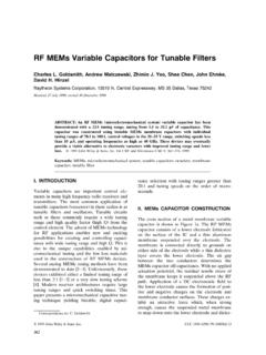
7 DEVICE StructureThe DEVICE used in this study is a state-of-the-art metal di-electric metal RF MEMS capacitive switch fabricated on aglass substrate. Fig. 1 shows the top view of a microencapsu-lated switch and the cross-section drawing of the switch [12].The dielectric is sputtered silicon dioxide with a thickness and a dielectric constant of The top electrode isa flexible aluminum membrane that is DC andRF grounded. The bottom chromium/gold electrode serves asthe center conductor of a 50coplanar waveguide for the RFsignal. The actuation voltage of the switch is approximately22 V. Without any electrostatic force, the membrane is nor-mally suspended in air above the dielectric .
8 Controlvoltage with a magnitude of 25 35 V is applied to the bottomelectrode, which brings the membrane in contact with thedielectric thus forming a 120m80m capacitor to shuntthe RF signal to ground. When the control voltage is reducedto below the release voltage of 8 V, the membrane springs backto its fully suspended position, resulting in little capacitive loadto the RF signal. The switch has low insertion loss ( dB)and reasonable isolation (15 dB) at 35 GHz. The switching1530-4388/$ 2006 IEEEYUANet al.: acceleration OF dielectric charging IN RF MEMS CAPACITIVE SWITCHES557 Fig. 1. (a) Top view of a state-of-the-art microencapsulated RF MEMS capac-itive switch.
9 (b) Cross-section view (not to scale) of the RF MEMS capacitiveswitch. Control voltage is applied between the bottom and top electrodes of is less than 10s. Details of the design, fabrication andperformance of the switch were reported in [1].B. Transient Current MeasurementsIn order to extract the temperature-dependent chargingmodel, charging and discharging transient currents were mea-sured under different temperatures on large500m500mmetal insulator metal (MIM) capacitors with the same elec-trode and dielectric material as the switch. A precisionsemiconductor parameter analyzer (Agilent 4156C) was usedto force a30-V pulse on the bottom electrode of the MIMcapacitor while sensing the transient current.
10 Well-guardedprobe station and probes were used to suppress the capacitiveand leakage currents in the measurement path, thus extendingthe transient current measurement range below picoampere(pA) a voltage pulse is applied to an MIM capacitor, thetotal current across the capacitor includes displacement current,trap charging current, and steady-state leakage current. Sincethe time constant for the displacement current is of the order ofmilliseconds, the transient currents measured in seconds com-prise mainly trap charging currents. Similarly, transient currentsmeasured in seconds after the voltage pulse is removed comprisemainly trap discharging currents.