Transcription of RF MEMS-Based Tunable Filters - MEMtronics
1 RF MEMS-Based Tunable Filters James Brank, Jamie Yao, Mike Eberly, Andrew Malczewski, Karl Varian, Charles Goldsmith Raytheon Systems Company, P. O. Box 660246 MS 35, Dallas, Texas 75266. Accepted 17 May 2001. ABSTRACT: This paper overviews the application of RF mems switches in Tunable lters as well as circuit developments for bandpass lters covering 110 MHz to GHz. RF mems . have several desirable features, including small size, low power requirements, and low loss. The basic operation of Raytheon's RF mems capacitive membrane switch is described. An overview of the technique used to integrate the switch into a variable capacitor structure with sixteen capacitance states is provided.
2 Variable capacitor structures are used to construct multipole lumped bandpass lter designs, each with sixteen states. Finally, measured data from two representative ve- and six-pole bandpass lters are presented. Characterization data demonstrates that the insertion loss for the ve-pole lter using on-chip inductors was between and dB, and between and dB for the six-pole lter using off-chip inductors. 2001 John Wiley & Sons, Inc. Int J RF and Microwave CAE 11: 276 284, 2001. Keywords: mems ; microelectromechanical system; Tunable capacitors; varactors; membrane capacitor; Tunable lter; Tunable bandpass lter I. INTRODUCTION resonator component that affords the high perfor- mance achieved by xed resonators.
3 YIG lters Filters are the basic building blocks within fre- come the closest to having very good lter selec- quency converting systems such as receivers and tivity, but at the expense of being bulky, requiring tuners. At microwave frequencies (1 GHz and signi cant quiescent current, and being expensive. above), lters are composed of high-Q resonators To date, diode varactor-tuned circuits, though such as printed transmission line, suspended rods, simple and requiring little bias current and size, or dielectric pucks. Depending on the media have not met the expectations of most modern used to create these resonators, excellent perfor- receiver requirements in terms of loss.
4 As such, mance can be achieved with Qs in the hundreds inexpensive and high performance Tunable res- for printed lines to tens of thousands for dielec- onators have become one of the holy grails of tric resonators. The need for frequency tunability receiver components. within broadband receiving and transmitting sys- The advent of microelectromechanical sys- tems usually necessitates switching of multiple tems ( mems ) for radio-frequency (RF) appli- xed-tuned circuits. The use of Tunable lters and cations provides new possibilities for achieving resonators can signi cantly simplify complexity the desired characteristics of a Tunable resonator. and reduce losses within complex multiband sys- RF mems devices, a new paradigm in the con- tems.
5 Unfortunately, there is not yet a Tunable struction of electronic devices, created mechan- ical structures on the microscale. Being con- Correspondence to: James Brank structed entirely of low-loss metals and dielectrics, Contract grant sponsor: Raytheon. these mechanical structures inherently have low Contract grant number: DARPA F 30602-97-C-D1 8la, loss. 2001 John Wiley & Sons, Inc. 276. RF MEMS-Based Tunable Filters 277. Development of RF mems switches has been Top View under way seriously since about 1995 from several Membrane industrial and university groups. These devices have distinguished themselves as having very low Undercut loss, requiring practically no power consumption, Access Holes and having very high linearity.
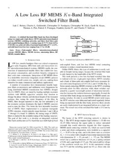
6 The application Signal Path of RF mems has already proven to provide Lower revolutionary (rather than evolutionary) improve- Electrode ments in electronic switching performance for Dielectric phase shifters at microwave and millimeter-wave frequencies. This paper explores the use of RF mems Post Cross Section capacitive switches in the application of tun- Dielectric Electrode able lters. Since these devices are operated in a bistable manner, with either a high or low capaci- Buffer Layer tance, they are a natural device for accomplishing digital frequency selection within a lter. The High resistivity silicon capacitive membrane switch is used to create a Figure 2. Views of the RF mems capacitive switch.
7 Multibit variable capacitor which serves as a dig- [Color gure can be viewed in the online issue, which is ital varactor. This varactor is in turn used within available at ]. resonators and coupling circuits to create Tunable , lumped-element LC lters for receiver front-end applications. The basic RF mems capacitive switch is shown in Figure 2. The structure is basically a parallel-plate capacitor with a movable top plate. II. mems VARIABLE CAPACITOR Applying a voltage between the membrane (top CONSTRUCTION/ ELECTRICAL plate) and electrode (bottom plate) creates an PERFORMANCE electric eld. When the eld is strong enough, the membrane will ex downward and contact the To create variable capacitors, xed MIM capaci- dielectric.
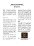
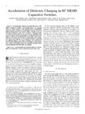
8 A simple electrical model of the switch tors are combined in series with RF mems capac- is shown in Figure 3. Typical on capacitance itive switches as shown in Figure 1. This creates a (membrane down) is 3 pF, and off capacitance two-state capacitor whose value is set by the series (membrane up) is 30 fF, [2, 3]. combination of the xed cap and the capacitance The xed capacitor used were metal-insulator- of the RF mems . The minimum value of the two- metal (MIM) capacitors, as shown in Figure 4. state capacitor is limited by the off-capacitance of Both top and bottom plates of the capacitor are the mems , and the maximum value is limited gold, with a thin silicon nitride dielectric layer by the on-capacitance of the RF mems .
9 Gen- ( r = 6 8). Average capacitance, resistance, and erally, the value of the xed cap is kept below Q at 1 GHz for four MIM test structures are the on-capacitance of the mems switch to mini- shown in Table I. It should be noted that when mize the effect of mems variation. Combinations measuring high-Q devices it can be dif cult to of these two-state capacitors with xed capacitors extract accurate values for Q. The Q values are allow construction of variable capacitor structures, ref. [1]. RSE RSE. Fixed RF CON/OFF. Cap mems . RSH RSH. Figure 3. Simple schematic of the RF mems capac- Figure 1. Schematic of a two-state variable capacitor itive switch. [Color gure can be viewed in the online using RF mems .]
10 Issue, which is available at ]. 278 Brank et al. C4. C3. Control Lines C2. C1. C0. Figure 5. Schematic of a four-bit variable capacitor using RF mems . Figure 4. Layout of a MIM capacitor. very sensitive to small errors in R and can be dif cult to extract. Other measurements of simi- lar capacitors yielded Qs that varied by as much as 100%. This large variation depends upon the speci c measurement conditions, such as the calibration method used or the condition of the RF probes. The schematic of a four-bit variable capaci- tor is shown in Figure 5. It consists of ve xed capacitors, four of which are in series with an RF. mems capacitive switch. A layout of a four-bit Figure 6.