Transcription of Wafer Level micro-Encapsulation - MEMtronics
1 Wafer Level micro-Encapsulation David I. Forehand and Charles L. Goldsmith MEMtronics Corporation Plano, Texas, USA 75075 Abstract: Wafer - Level micro-Encapsulation is an innovative, low-cost, Wafer - Level packaging method for encapsulating RF MEMS switches. This zero- Level packaging technique has demonstrated < dB package insertion loss up through 110 GHz and accounts for only 28% of the total packaged RF MEMS circuit cost. This article overviews the processes, measurements, and testing methods used for determining the integrity and performance of individual encapsulated RF MEMS packages. Keywords: RF MEMS; low loss; packaging; Wafer - Level ; hermeticity; humiticity. Introduction RF MEMS switch reliability, packaging, and cost issues severely limit their use in military, space, and commercial applications, despite their demonstrated performance advantages.
2 Switch packaging is quickly moving to the forefront as the dominant problem to be solved, since it significantly impacts both switch reliability and cost. Conventional packaging methods have come up short in both cost and loss. Standard ceramic microwave packages cost ~$50 each and have losses which are generally greater than the MEMS circuit they are trying to protect. Consequently, most MEMS development efforts are focused on reducing loss and cost utilizing Wafer - Level packaging (WLP) such as Wafer bonding using anodic bonding, metal-metal, or glass-frit seals. However, these WLP techniques suffer from high cost (70-80% of total device cost) and require either hermetic via interconnects inside the package or careful design to obtain moderate interconnect losses through the seal ring. This seal ring occupies significant area and decreases the number of potential devices per Wafer .
3 In addition, most WLP techniques are not easily scalable to different RF device sizes, types, or frequencies. A promising Wafer - Level packaging alternative to Wafer -bonding is Wafer - Level micro-Encapsulation (WL E). With this technique, individual cages are constructed over each switch using the same sacrificial micromachining techniques used to fabricate the RF MEMS switches [1]. Unlike most other WLP schemes, WL E requires no special RF transition through the package to achieve extremely low-loss and is easily scalable to different RF device sizes, types, or frequencies. A key challenge with the ~1 nL cavities of WL E is to demonstrate good switch lifetimes in harsh environments. Fabricating and measuring the desired environment in nL-scale packages poses unique challenges. The He fine leak testing of MIL-883D is not fully applicable for cavity volumes <1,000 nL [2].
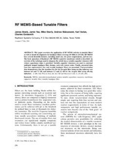
4 Fortunately, unlike resonators, the operation of RF MEMS switches is not adversely affected by oxygen, nitrogen, or helium. Instead, RF MEMS switch operation is very sensitive to humidity levels because the surface tension of adsorbed water molecules is sufficient to overcome the membrane restoring force and create stiction. For a switch design with a spring constant of 5-10 N/m, water vapor induced stiction at room temperature occurs between 30-50% RH. Therefore, humiticity test procedures are being developed to investigate water diffusion into the micro-packages, utilizing dew point sensors and accelerated testing similar to [3]. Process Wafer - Level micro-encapsulated humidity sensors were fabricated on 150 mm Corning 7740 glass substrates and are shown in Figure 1. The dew point sensors consist of interdigitated electrodes in three size variations; m, 5 m, and 10 m lines and spaces.
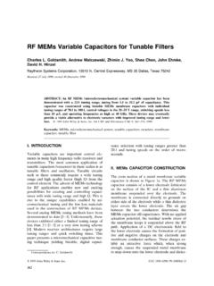
5 These comb structures were fabricated in the switch electrode layer. The mask set was designed to simultaneously build the sensors and RF MEMS switches on the same Wafer . A schematic cross-section of a WL E RF MEMS switch package is shown in Figure 2. A conventional switch process sequence through membrane pattern was utilized as: 1) Wafer clean, 2) deposit/pattern/etch (D/P/E) 300 nm gold electrode, 3) D/P/E 250 nm SiO2 switch dielectric, 4) electroplate m copper transmission lines, 5) pattern organic sacrificial layer, and 6) D/P/E 350 nm aluminum alloy membrane. Figure 1. Photo of a microencapsulated package containing a dew-point sensor. 320 Instead of releasing the membrane at this point in the process flow, as would occur for unpackaged switches or other packaging schemes, an additional cage sacrificial layer was applied over the unreleased switch membrane.
6 Next the dielectric cage was deposited. This cage sacrificial layer creates the desired separation between the membrane and packaging cage. Figure 2. A cross-section of the microencapsulated package reveals a cage, encapsulation, and a sealant protecting the MEMS switch inside. Holes were patterned and etched into the cage and the sacrificial layers were plasma etched to create a released switch with a packaging superstructure above it. After release, a liquid encapsulant, such as spin-on-glass (SOG) or Cyclotene series 4000 benzocyclobutene (BCB), was applied over the entire Wafer while in a dry nitrogen atmosphere. The surface tension of the SOG or BCB ensures that it covers the cage structure but does not wick through the cage holes to encroach onto the switch. The SOG or BCB was then cured at 250 C to form a closed seal over the switch.
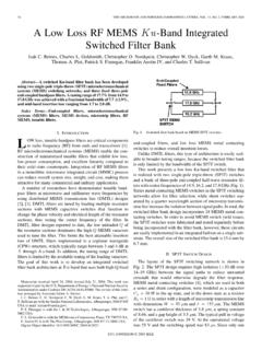
7 At this point in the process flow, the micro-Encapsulation provides the minimum Level of protection from humidity. Additional sealant overcoats can be applied to increase the Level of protection. However, to ascertain the minimum humidity protection of micro-Encapsulation , some packaged dew point sensors were subjected to accelerated lifetime testing after the BCB was cured. Results RF Measurements - Detailed RF measurements up to W-band have been made on the packaging structures created by Wafer - Level micro-Encapsulation . Measurements were made on a Cascade Summit 12000 test station connected to an Agilent 8510C vector network analyzer. Calibration was accomplished using Cascade s WinCal software with a probe-tip calibration (LRRM). Figure 3 demonstrates the insertion loss through 110 GHz for a simple transmission line and a transmission line with a microencapsulated package on top.
8 The difference in insertion loss is barely discernable in this measurement. Similarly, the return losses of both structures are shown in Figure 3. The return loss shows an excellent impedance match across the band of measurement. More detailed measurements have been performed over the 8-50 GHz range with a single-delay TRL calibration to de-embed all but the package performance. These measurements reveal an insertion loss on the order of dB at 35 GHz. Thru linePackage (cage + encapsulant)Thru linePackage (cage + encapsulant)Insertion LossReturn Loss Figure 3. Comparison of transmission line and package losses reveals very little package loss up through 110 GHz. Humiticity: The dew point sensors were tested by measuring current versus voltage, in a Cascade Attoguard test station with a Keithley S4200 semiconductor parameter analyzer.
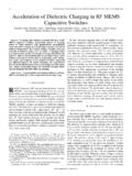
9 To characterize the m sensor baseline operation, several micro-packages were pierced to allow either dry nitrogen or humid cleanroom air (20 C, 45% RH, dew point ~7 C) to contact the sensor. The baseline sensors were baked out in dry nitrogen at 115 C for 10 minutes. Current-voltage measurements were taken in dry nitrogen with chuck temperatures of 100 C, 75 C, 50 C, 25 C, and 0 C. Figure 4 show the I-V data for 100 C, 25 C, and 0 C. The current decreases with decreasing temperature. The measurement noise floor was measured with the probes in the up/open position and is shown in the bottom trace of each graph. The dry nitrogen was turned off and the front panel of the test station was opened to allow the environment to reach equilibrium with the cleanroom air. The resulting I-V data for chuck temperatures of 25 C and 2 C are shown in Figure 5.
10 As expected, the 2 C data shows a >106 increase in current, indicating the sensor is very sensitive to condensation. Comparing the 25 C dry nitrogen to humid cleanroom air data, Figures 4 and 5, the average current at 40V of the dew point sensors increases from ~7x10-13 A to ~4 x10-11 A. This 60x increase in current is caused by the thin adsorbed water layer. The humid cleanroom air approximates where RF MEMS switches have been observed to exhibit water related stiction failure. A dew point sensor current of 4 x10-11 A at 40V will be used to approximate this condition. GlassSubstrateSubstrateGround PlaneElectrodeTransmissionLinesMe mbr a neCage St r uct ureEncaps ulantSwi tchDielectricDevice/PackageCross-Secti onSealant32125C100C0C Figure 4 I-V calibration curves for dew point sensors under dry conditions. 02C Humid25C Humid Figure 5 I-V calibration curves for dew point sensors under humid conditions.