Transcription of RF MEMs Variable Capacitors for Tunable Filters - …
1 RF mems Variable Capacitors for Tunable FiltersCharles L. Goldsmith, Andrew Malczewski, Zhimin J. Yao, Shea Chen, John Ehmke,David H. HinzelRaytheon Systems Corporation, 13510 N. Central Expressway, MS 35 Dallas, Texas 75243 Recei ed 27 July 1998; re ised 30 December 1998()ABSTRACT: An RF mems microelectromechanical system Variable capacitor has beendemonstrated with a 22:1 tuning range, tuning from to pF of capacitance. Thiscapacitor was constructed using bistable mems membrane Capacitors with individualtuning ranges of 70:1 to 100:1, control voltages in the 30 55 V range, switching speeds lessthan 10mS, and operating frequencies as high as 40 GHz. These devices may eventuallyprovide a viable alternative to electronic varactors with improved tuning range and John Wiley & Sons, Inc.
2 Int J RF and Microwave CAE 9: 362]374, : mems ; microelectromechanical system; Tunable Capacitors varactors; membranecapacitor; Tunable filterI. INTRODUCTIONV ariable Capacitors are important control ele-ments in many high frequency radio receivers andtransmitters. The most common application of . Tunable Capacitors varactors in these radios is astunable Filters and oscillators. Tunable circuitssuch as these commonly require a wide tuning .range and high quality factor high Q from thecontrol element. The advent of mems technologyfor RF applications enables new and excitingpossibilities for creating and controlling capaci-tance with wide tuning range and high Q. This isdue to the unique capabilities enabled by mi-cromechanical tuning and the low loss materialsused in the construction of RF mems analog mems tuning methods have beenwxdemonstrated to date 1]4.
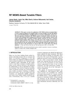
3 Unfortunately, thesedevices exhibited either a limited tuning range ofwxless than 2:1 1]3 or a very slow tuning schemewx4 . Modern receiver architectures require largetuning ranges and quick switching times. Thispaper presents a micromechanical capacitive tun-ing technique yielding bistable, digital capaci-Correspondence to: C. Goldsmithtance selection with tuning ranges greater than20:1 and tuning speeds on the order of mems CAPACITOR CONSTRUCTIONThe cross section of a metal membrane variablecapacitor is shown in Figure 1a. The RF MEMscapacitor consists of a lower electrode fabricatedon the surface of the IC and a thin aluminummembrane suspended over the electrode. Themembrane is connected directly to grounds oneither side of the electrode while a thin dielectriclayer covers the lower electrode.
4 The air gapbetween the two conductors determines theMEMs capacitor off-capacitance. With no appliedactuation potential, the residual tensile stress ofthe membrane keeps it suspended above the RFpath. Application of a DC electrostatic field tothe lower electrode causes the formation of posi-tive and negative charges on the electrode andmembrane conductor surfaces. These charges ex-hibit an attractive force which, when strongenough, causes the suspended metal membraneto snap down onto the lower electrode and dielec-Q1999 John Wiley & Sons, 1096-4290r99r040362-13362RF mems Variable Capacitors for Filters363 Figure of an RF mems capacitor in ..the unactuated a and actuated b surface, forming a low impedance RF path toground. Figure 1b demonstrates an RF MEMscapacitive capacitor in the actuated state.
5 In thisstate, the characteristics of the dielectric layerprimarily determine the mems virtue of changing the position of the mem-brane with an applied DC voltage, the capaci-tance of this RF mems device can be changedover a significant capacitance RF mems Capacitors described in thisarticle are built on high resistivity silicon sub- .strates)10 kVcm , with a 1mm thick layer ofsilicon dioxide used as a buffer layer. The capaci-tor circuitry is fabricated on top of the silicondioxide using thick aluminum intercon-nects which are compatible with CMOS circuitryand exhibit low conductor losses at high frequen-cies. The bottom electrode of the Capacitors isbuilt of refractory metal. Thisfilm provides good conductivity for low loss andhas a smooth surface finish.
6 This finish is impor-tant for achieving good contact between themembrane and the lower electrode, minimizingany air gap. On top of the lower electrode is afilm of silicon nitride, less than thick. Thisfilm blocks the DC control signal from shortingout during capacitor actuation, yet allows RFsignals to capacitively couple from the lower elec-trode to the upper membrane. The metallic ca-pacitor membrane consists of a thin aluminumlayer less than thick. This membrane hashigh conductivity for low RF resistance and goodmechanical properties. The suspended metalmembrane spans two grounded posts. A series of2mm holes is patterned throughout the uppermembrane to accelerate the removal of the sacri-ficial polymer from beneath the membrane.
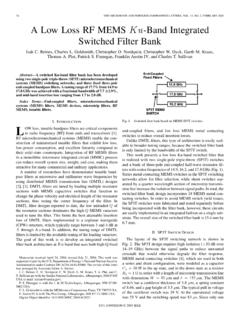
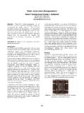
7 Re-moving this material mechanically releases themembrane, freeing it to move up and down ontothe lower electrode in response to applied elec-trostatic forces. A top view of the completed RFMEMs capacitor is shown in Figure 2. The size ofthe signal path line is 120mm wide, while the sizeof the membrane is approximately 120mminwidth and spans 280mm from ground to mems CAPACITOR FABRICATIONS urface micromachining techniques were utilizedto fabricate the RF mems Capacitors describedabove. Figure 3 demonstrates the essential pro-cess steps: 1 A thick insulating thermal oxide isgrown on the substrate. 2 A thin layer of refrac-tory metal is deposited and patterned to definethe capacitor electrodes. 3 A layer of PECVD silicon nitride is deposited and patterned to formFigure view of a shunt mems et flow for fabrication of a capacitor dielectric.
8 4 A thick layer of alu-minum is evaporated and patterned to define themetal transmission lines and the mechanical sup-port posts for the capacitor. 5 A polymer sacrifi-cial layer is spin coated and patterned. 6 Analuminum film is deposited and patterned to de-fine the capacitor membrane. 7 The sacrificiallayer is removed by a plasma etch through accessholes and the edges of the mems CAPACITOR ELECTRICALPERFORMANCEC haracterization of the RF mems capacitor con-trol element consists of two-ports-parametermeasurements of a shunt RF mems capacitorsituated in the middle of a 50 Vtransmissionline. Measurements of thes-parameters of the ..capacitor in actuated on and unactuated offstates yields information regarding resistances andreactances at frequencies throughout the mi-crowave measurementswere performed over the ]40 GHz frequencyrange using a Wiltron 37279 vector network ana-lyzer and a Cascade Summit 10000 RF probingsystem.
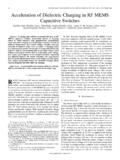
9 DC resistance measurements were madewith a Fluke 8840A multimeter connected to DCprobes. From these measurements, an equivalentcircuit model was extracted to determine capaci-tor element physically based electrical model of the RFMEMs capacitor is shown in Figure 4. The twoseries resistors,R, model the contact and pathSEresistance of the capacitor lower electrode. Theshunt resistors,R, represent the resistive lossSHfrom the center of the capacitor element, throughthe membrane, to ground. As the membrane andelectrode are physically thin compared to a skindepth at microwave frequencies, the DC and RFresistances for these physical elements are ap-proximately equal. The capacitance of the mem-brane in the unactuated state,C, is a functionOF Fof the area of the membrane and lower electrode,and the height of the air gap.
10 The capacitance of .the membrane in the actuated stateCis aONfunction of the area, thickness, dielectric con-stant, and surface finish of the dielectric layer. Asthe capacitor element is physically small com-pared to a wavelength at microwave frequencies,representation of this device as a lumped capaci-tor is measurements of the lower elec-trode yield approximately to resis-tance from end to end. Therefore,Ris approxi-SEmately to Resistance measurements ofFigure model of a mems mems Variable Capacitors for Filters365the membrane from end to end yields approxi-mately ,soRis approximately reactance of the capacitor membrane wasdetermined based on the insertion and isolationperformance of the two-port device at to the low loss of the RF mems capaci-tors in the off-state, direct measurement of inser-tion loss tends to be inaccurate.