Transcription of 7. Transonic Aerodynamics of Airfoils and Wings
1 Mason3/10/067. Transonic Aerodynamics ofAirfoils and IntroductionTransonic flow occurs when there is mixed sub- and supersonic local flow in the same flowfield(typically with freestream Mach numbers from M = or to ). Usually the supersonicregion of the flow is terminated by a shock wave, allowing the flow to slow down to subsonicspeeds. This complicates both computations and wind tunnel testing. It also means that there is verylittle analytic theory available for guidance in designing for Transonic flow conditions. Importantly,not only is the outer inviscid portion of the flow governed by nonlinear flow equations, but thenonlinear flow features typically require that viscous effects be included immediately in theflowfield analysis for accurate design and analysis work. Note also that hypersonic vehicles withbow shocks necessarily have a region of subsonic flow behind the shock, so there is an element oftransonic flow on those vehicles the days of propeller airplanes the Transonic flow limitations on the propeller mostly keptairplanes from flying fast enough to encounter Transonic flow over the rest of the airplane.
2 Here thepropeller was moving much faster than the airplane, and adverse Transonic aerodynamic problemsappeared on the prop first, limiting the speed and thus Transonic flow problems over the rest of theaircraft. However, WWII fighters could reach Transonic speeds in a dive, and major problems oftenarose. One notable example was the Lockheed P-38 Lightning. Transonic effects prevented theairplane from readily recovering from dives, and during one flight test, Lockheed test pilot RalphVirden had a fatal accident. Pitching moment change with Mach number (Mach tuck), and Machinduced changes in control effectiveness were major invention of the jet engine allowed aircraft to fly at much higher speeds (recall that theGermans used the Me 262 at the end of WWII, in 1944, and the Gloster Meteor was apparently thefirst operational jet fighter). Since the advent of the jet engine, virtually all commercial transportsnow cruise in the Transonic speed range.
3 As the Mach number increases, shock waves appear in theflowfield, getting stronger as the speed increases. The shock waves lead to a rapid increase in drag,both due to the emergence of wave drag, and also because the pressure rise through a shock wavethickens the boundary layer, leading to increased viscous drag. Thus cruise speed is limited by therapid drag rise. To pick the value of the Mach number associated with the rapid increase in drag, weneed to define the drag divergence Mach number, MDD. Several definitions are available. The oneused here will be the Mach number at which dCD/dM = Mason, Configuration Aerodynamics3/10/06 After WWII, it was found that the Germans were studying swept Wings to delay the drag riseMach number. Allied examination of German research led to both the North American F-86 and theBoeing B-47 designs being changed to swept wing configurations.
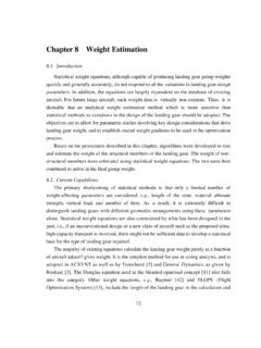
4 The idea of swept Wings can betraced to Busemann s Volta conference paper of 1935, and the wartime ideas of Jones at theNACA. Ironically, the airplane used for the first manned supersonic flight (the X-1, in 1947), didnot use a jet engine or wing sweep. It was a rocket powered straight wing airplane. However, shortlythereafter, the F-86, a swept wing jet powered fighter, went supersonic in a shallow , advances in one technology, propulsion, had a major impact on another, Aerodynamics ,and illustrates the need to carefully integrate the various technologies to achieve the best totalsystem performance. The formal process of performing this integration has become known asmultidisciplinary design optimization (MDO). Physical aspects of flowfield development with Mach 7-1, taken from the classic training manual, Aerodynamics for Naval Aviators,2 shows thedevelopment of the flow with increasing Mach number, starting from subsonic speeds.
5 At somefreestream Mach number the local flow becomes sonic at a single point on the upper surface wherethe flow reaches its highest speed locally. This is the critical Mach number. As the freestreamMach number increases further, a region of supersonic flow develops. Normally the flow is broughtback to subsonic speed by the occurrence of a shock wave in the flow. Although it is possible todesign an airfoil to have a shock-free recompression, this situation is usually possible for only asingle combination of Mach number and lift coefficient. As the Mach number increases, the shockmoves aft and becomes stronger. As the Mach number continues to increase, a supersonic regionand shock wave also develops on the lower surface. As the Mach number approaches one, theshocks move all the way to the trailing edge. Finally, when the Mach number becomes slightlygreater than one, a bow wave appears just ahead of the airfoil, and the shocks at the trailing edgebecome oblique.
6 These shock waves are the basis for the sonic boom. Many variations in thespecific details of the flowfield development are possible, depending on the specific geometry of typical progression of the flow pattern, as shown in Figure 7-1, leads to rapid variations indrag, lift and pitching moment with change in Mach number. Today we can predict these variationscomputationally. However, when these changes were initially found in flight, they were dangerousand appeared mysterious to designers because there was no understanding of the fluid mechanicsof the that problems with pitching moment variation with Mach number and the flowfield over acontrol surface using a hinged deflection led to the introduction of the all-flying tail in the X-1 andlater models of the F-86. Subsequently, all-flying tails became standard on most supersonic tacticalaircraft.
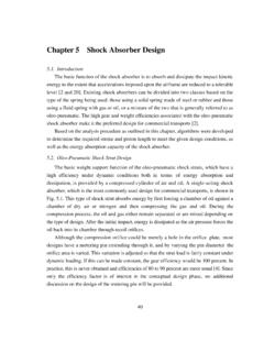
7 This was considered an important military advantage, and was classified for several Aerodynamics of Airfoils and Wings 7-33/10/06 Based on military experience, Lockheed used an all-flying tail on the L-1011, while the othertransport manufacturers continued to use a horizontal tail and 7-1. Progression of shock waves with increasing Mach number, as shown inAerodynamics for Naval Aviators,2 a classic Navy training manual (not copyrighted). Technology The slotted wall wind tunnelSeveral advances in technology were key to our ability to design efficient Transonic aircraft. Theproblem with wind tunnel testing was the reflection of shocks from the tunnel walls and the7-4 Mason, Configuration Aerodynamics3/10/06tendency of the flow to choke as it went past the model. Wind tunnel results were completelywrong. The invention of the slotted wall wind tunnel at NACA Langley in the late 1940s allowed thetunnel interference effects to be significantly reduced, and led to practical wind tunnel testingmethods.
8 A chapter in Becker s book describes how this capability came The slots areclearly shown in Figure 7-2. Using the 8-foot slotted wall wind tunnel at NASA Langley,Whitcomb, who had earlier developed the area rule, made a breakthrough in airfoil design. Hissupercritical airfoil designs spurred renewed interest in airfoil design for increased efficiency attransonic His group also had to figure out how to simulate the full scale Reynolds numberat sub scale Finally, in the early 1970s, breakthroughs in computational methodsproduced the first Transonic airfoil analysis codes, which are described briefly in the next 7-2. A slotted wall wing tunnel test section. This picture is of a small blow-downtunnel design that was used to validate the concept before the largecontinuous-flow tunnels were constructed at NACA Langley ResearchCenter. This specific tunnel is a copy of the one made at Langley and wasconstructed by Republic Aviation in Farmingdale, NY.
9 When Fairchildaviation purchased Republic, Grumman Aircraft bought the Computational challenges/methodsThe theoretical/computational Transonic flow problem was very hard. Initially, very few analytic ornumerical methods were available. By 1970, everybody was trying to come up with a method tocompute the Transonic flow over an airfoil (the blunt body problem , which was important inpredicting the flowfield at the nose of re-entering ballistic missiles and the manned space program, Transonic Aerodynamics of Airfoils and Wings 7-53/10/06had just been conquered, see Chapter 11). The Transonic problem is difficult because it is inherentlynonlinear, and the steady solution changes math types, being elliptic in the subsonic portion of theflow and hyperbolic in the supersonic part of the flow. Earll Murman and Julian Cole made themajor Using Transonic small disturbance theory, they came up with a scheme thatcould be used to develop a practical computational method.
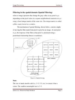
10 Equation 7-1 illustrates how thenonlinear term in the equation allows for the equation to change type, and indeed provides a way forthe type to be found locally in a computational scheme. 1 M 2 +1()M 2 x >0elliptic PDE<0hyperbolic PDE xx+ yy=0(7-1)In Murman and Coles s scheme shocks emerged naturally during the numerical solution of theequation. Essentially, they used finite difference approximations for the partial derivatives in thetransonic small disturbance equation. The key to making the scheme work was to test the flow ateach point to see if the flow was subsonic or supersonic. If it was subsonic, a central difference wasused for the second derivative in the x-direction. If the flow was supersonic, they used an upwinddifference to approximate this derivative. This allowed the numerical method to mimic the physicalbehavior of the flowfield.