Transcription of A Practical Guide To Cable Selection
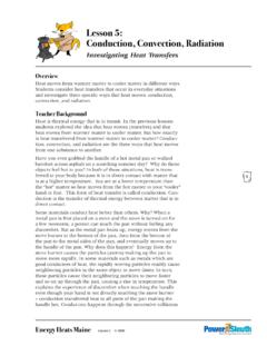
1 A Practical Guide To Cable SelectionLiterature Number: SNLA164A Practical Guide To INTRODUCTIONThis application note provides an overview of the variousconsiderations necessary for selecting suitable copper multi-conductor or twisted pair cables for use with standard inter-face devices. It is important that a Cable is well matched tothe application; as well as, that the various Cable selectiontrade-offs are considered for a cost effective system types, constructions, and characteristics are coveredand then related to the various device TYPES OF CABLESThe two most basic Cable categories are flat and round (seeFigure 1andFigure 2). Both flat and round cables are avail-able in multiconductor or twisted pair configurations andeach with or without shielding. Shielding of various types isalso available in both cases. Flat cables have carefully con-trolled conductor spacing making them suitable for mass ter-mination.
2 Round cables are suited for long Cable runs orwhere flexibility and compactness are cables are available for basic single-ended, , unbalanced applications. Twisted pair cables are avail-able for differential, , balanced applications (Figure 3).Note that a coaxial Cable , a single insulated conductor withan overall shield; is, in this context, a multiconductor cablewith only one conductor (the shield serving the dual purposeof signal return path and signal containment). In a similarsense, a two conductor multiconductor Cable , since it istwisted, is equivalent to a single twisted pair is a registered trademark of Elf is a registered trademark of Dupont de Nemours 1. Drawing of Flat Cable , Cross-SectionAN011937-2 FIGURE 2. Drawing of Round Cable , Cross-SectionNational SemiconductorApplication Note 916 David HessJohn GoldieOctober 1993A Practical Guide to Cable SelectionAN-916 1998 National Semiconductor is common and preferable to use a twisted pair Cable forsingle-ended applications.
3 Some higher speed or longer dis-tance single-ended applications provide a separate returnconductor for each data and timing circuit, helping to reducecrosstalk. Note that single-ended applications cannot fullyutilize the special capability of a twisted pair. Multiconductorcable should not be used for differential applications wheretwisted pairs are is important to recognize that a twisted pair serves a funda-mental electrical purpose. A twisted pair maintains, along itslength, the balance necessary for and thus the commonmode rejection sought in differential applications. The de-gree of physical symmetry achieved in constructing a twistedpair of insulated conductors determines how well it is bal-anced electrically. The double helix configuration of the pairproduces symmetrical parasitics for each conductor. Sym-metrical parasitics assure that induced noise signals areequal, or common , to both conductors.
4 This is the primarymeans of reducing crosstalk between various circuits withina Cable . Flat cables constructed with twisted pairs are alsoavailable to achieve improved crosstalk of Flat CablesBy providing a means for mass termination, flat cables arerelatively inexpensive to terminate. Connectors are availablein configurations with insulation displacement contactsaligned for flat Cable termination. The contacts are simulta-neously pressed through the insulation onto all of the con-ductors of a flat Cable . The Cable conductor to connectorcontact alignment is critical. The two industry standard con-ductor centerline spacings are and inches. Con-trolling this parameter is a primary concern in producing flatcable and somewhat limits the range of cables electricalcharacteristics of Round CablesRound Cable flexibility is not limited to a single plane, as inthe case of flat Cable .
5 For long Cable runs, especially in-stalled in conduit or raceway, flat Cable is impractical. Theflexibility of round cables is the result of having the individualelements, single conductors or twisted pairs, cabled ; thatis, they are laid at a pitch angle relative to the axis of thecable, forming a helix. The greater the pitch angle thegreater the degree of flexibility. Color coding is usually pro-vided as the means of identifying the individual conductorsaiding the process of individually terminating each conduc-tor. A round Cable is simpler to manufacture with a can be reduced with thicker insulation walls,since there are no inherent conductor spacing than the case of simple, flat, strait, unshielded multi-conductor cables; round cables have less cross-sectionalarea for a given number of conductors. More cross-sectionalarea is required for a shield or jacket on a flat Cable CONSTRUCTIONO verall ConstructionConductorsStandard subminiature D-style connectors are designed toaccept conductor sizes ranging typically from 22 AWG downto 26 AWG.
6 Stranded tinned copper is normally provides a considerable improvement in flexibilityand protection from conductor breaks due to repeated flex-ing, , improved flex life. Tin coating on the strands im-proves environmental resistance by preventing corrosion ofthe conductor. The tin coating also makes the conductormore suitable for soldering. Standard connector pins aresized to accept the stranded conductor s increased diametercompared to solid conductor or non-tinned conductors are not recommended foruse with some connectors. Some connector pins arecrimped onto the end of the conductor where a small sectionof the insulation has been removed. This leaves a short sec-tion of exposed conductor susceptible to corrosion. Giventhe minimal space provided within the connector backshell,the added flexibility of stranded conductor makes the job ofcramming the terminated conductors into the backshell a loteasier and more reliable.
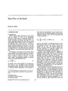
7 Conductor stranding also in-creases the overall Cable flexibility, easing installation, andmaking the Cable more likely to withstand the relatedabuses. If there will be even occasional flexing required inthe Cable application, stranded conductors are strongly cost savings are gained by eliminating stranding ortin coating, but consideration should be given to the reduc-tion in reliability. Stranding and tin coating have an effect onthe signal loss of a transmission line, but these effects are in-significant below frequencies of about 10 MHz. These effectsare essentially immeasurable at the frequencies associatedAN011937-3 FIGURE 3. Drawing Comparison of Multiconductor Cable and Twisted Pair current TIA data communication standards; furthermore,other far more predominant limiting factors arise at datarates greater than 1 typical serial data links, the de-facto standard gauge sizeis 24 AWG.
8 TIA/EIA interface standards recommendationsare based on 24 AWG. This is the appropriate size to usewith common subminiature D-style connectors. For smallerconductors to be properly captured in crimped contacts, spe-cial sized contacts may be required. Overall Cable size andweight reduction can be achieved using 26 AWG or smallerconductors at the expense of increased fragility. Note, thereare National Electrical Code restrictions that prevent conduc-tors smaller than 24 AWG from being used in premises com-munication applications. Smaller conductors are recom-mended for restricted applications, such as equipmentcables or where overall Cable size must be limited; say forwide parallel data links used in short distances, up to 10 or20 conductors cannot provide very much improvement inperformance. The overwhelming performance limiting factorin serial data communication systems is noise.
9 An attempt toincrease data rate and/or distance by increasing conductorsize and thus reducing attenuation, is likely to be offset bycrosstalk and other noise limitations. Consider, for instance,that EIA-422-A gives recommendations for transmission upto 1,200 meters (4000 feet) at data rates up to 90 kbps on 24 AWG Cable . Typical data communication applications fallwithin the restrictions imposed by the voltage drop limitationsof 24 AWG conductor. Special sized connector contacts maybe required for larger conductors come in standard sizes according to theAmerican Wire Gauge (AWG) system. A conductor gaugesize is based on its cross-sectional area, and thus DC resis-tance. The overall diameter of the conductor depends onwhether it is solid or stranded. Stranding is provided as ameans of improving flexibility and flex-life, and the strandbundle is twisted similarly and for the same reasons men-tioned above for the overall Cable .
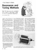
10 The basic stranding con-figuration is 7 strands; 6 around 1. For a given gauge size;the more strands, the more flexible. Stranded conductors areconsiderably more expensive than solid conductors and thecost increases with greater numbers of finer conductors utilize standard AWG size strands andnumbers of strands. Their size is designated by the largestAWG size less than or equal to the sum cross-sectional areaof the individual strands. Note, insulation displacement con-nector contacts are specifically designed for either solid orstranded 1. Conductors Solid Stranded Tinned and Bare from 30 AWG to 20 AWG vs Diameter DCR Weight, C. Resistance@20 CTin CoatedBare or Silver conductor, or individual strands in the case of strandedconductors, can be coated or bare . Tin is the most commoncoating. Diffusion of the tin coating into the surface of thecopper causes the DC resistance to be somewhat higherthan bare conductors, but this is a concern mainly at fre-quencies above 10 MHz.