Transcription of A shortened multi-band End-Fed Half Wave …
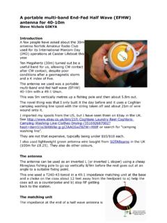
1 A shortened multi - band End-Fed Half Wave (EFHW) antenna for 80-10mSteve Nichols G0 KYAA shortened multiband antenna , about 23m long,for 80m-10m that offers low SWR ( :1) on 80mand 40m, and below 3:1 on 20, 15 and 10m. Theantenna has a full 300kHz bandwidth on 80mbetween 3:1 SWR points. But performance isdown about 8-12db on a dipole on antenna design came from attempts tofind an efficient 80m antenna that could fit into a small space. This was because Norfolk Amateur Radio Club likes to take part in the 80m Club Championship (we won in 2016), but many members don't have enough spacefor a full size (132ft) dipole or the 100-102 feet needed for a G5RV or W5GI antenna lets you get onto 80m in a horizontal distance of about 12m (40ft) when used as an inverted slope with the apex at take little credit for this as it was outlined in PD7 MAA's and IK0 IXI's blogs after extensive work on the antenna in the Netherlands.
2 However, there was little on their blogs in terms of its performance or SWR characteristics. Hence this antennaThe antenna can be used horizontally or as an inverted L (or inverted L sloper) that uses a cheap fibreglass fishing pole to go up vertically 8m before a further15m goes out or at an angle to a suitable fixing uses an FT140-43 or FT240-43 toroid in a 49:1 impedance matching unit at the base and a 110 micro Henry ( H) coil to act as a loading coil for 80m and achoke to stop higher frequencies using the last 2m of matching unitThe impedance at the end of a half wave antenna issomewhere between 2000-5000 Ohms.
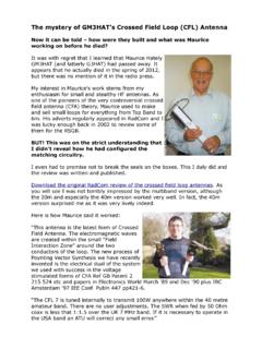
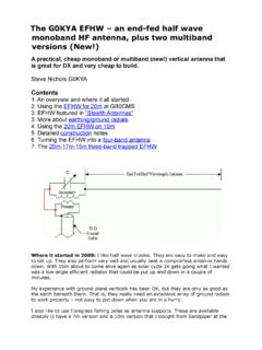
3 In otherdesigns, mine included, we make a resonant circuitusing a toroid coil and capacitor to resonate at thefrequency the PD7 MAA design (which is based on a lot ofwork done by Dutch amateurs) it uses an FT240-43as an autotransformer with two bifilar turns followedby 14 turns of the secondary to give an impedancestep-down of 7 squared or 49 , 2500 Ohms at the end of the EFHW is transformed down to around 50 Ohms and provides a better match to your , tests show that the FT240-43 doesn't work as a 49:1transformer across the whole of 80-10m, but is better at the bottom you don't have to put up with themismatch towards 10m as a capacitoracross the input helps reduce : Twisting the wire for thebifilar turns on the toroidWhen winding the toroid it is as wellto wrap white PTFE tape around thecore to stop arcing.
4 This is plumbers' tape and is very cheap on using an FT240-43, start by measuring out two pieces of 20 SWG enamelled copper wire one is about 1m, long and the other about 22cm. Twist the two together for the first 130mm, ensuring that you do this neatly. The twisted section then makes up the two bifilar turns on the add a further seven turns on the core before passing the wire across and under to the other side of the core and winding seven more, back in the opposite direction (see image). The wire should exit roughly opposite where you a 100pF high voltage capacitor across the centre pin and the earth on the input should improve the match at the top end.
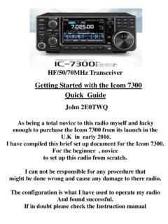
5 Some reports recommend a 150pF capacitor, but I found that this gave slightly higher SWR readings. A 100pF 3kV high voltage one is better and they are very cheap on alternative is to use an FT140-43 toroid, which is smaller (the 140 refers to the diameter, so ), which is good for at , some reports say thesmaller FT140-43 doesn't reallygive sufficient inductance on 80mand there are reports of it heatingup on 80m. I found that theFT140-43 DID work on 80m andseems to be able to take 100W forshort periods, with no fluctuation in SWRBut if you want to make an antenna that can run up to 200W I suggest you use the larger the FT140-43 for 50-100W maximum versions of the you want to make a 500W version use two FT240-43s stacked the antenna works as a multiple of half wave lengths on the higher bands:Loading CoilThe 110 H loading coil is used on the version for 80m.
6 The coil effectively stops the RF current flowing in the final 2m or so of wire at 7 MHz and also acts as a loading coil on 80m. I used standard 40mm PVC pipe from B&Q and 20 SWG enamelled copper wire, which is in diameter. To getto 110 F I used 76 turns. This is very tricky to do so I recommend fastening one end of the wire to the former (I used a solder tag and bolted it to the former) and then tape the wire down as you add turns. If you don't do this you can end up with a mess! Adding a final solder tag and bolting it to the former means you can then waterproof the whole coil with insulation you don't have 40mm pipe use an online inductance calculator to work out how many turns you need to get to 110 H.
7 This gives a reactance of K Ohms at earth or notConventional wisdom has it that you must have an a earth on a vertical antenna . This is true with a quarter wave antenna , which needs an extensive ground plane. With the EFHW the earth (or a counterpoise) is still important, but not quite as an earth the antenna will try and use the coax as the return path. The best way to resolve this is to fit a choke, such as 10 turns of RG213 on a four inch former or eight turns of RG58 through an FT240-43 ferrite toroid about a metre or so from the matching I connected the earth to an earth stake I found that the 3:1 SWR bandwidth on 80m halved.
8 With a choke fitted there is no sign or RF on the feed line at the operating position, with or without an earth tests shows no difference in performance if it was earthed or just relied on the choke. Given the restricted bandwidth on 80m if it is earthed I suggest you try it with a choke on its own and see how you the antennaThis can be quite tricky. I found the best way was to build the antenna , complete with the end piece of for 80m. Then tune the antenna up on To do this you will have to shorten the section between the loading coil and the matching unit. Do a little bit at a time as it can make a big difference.
9 Remember if the lowest SWR point is below it is too long, above it is too you have 40m tuned turn your attention to the piece after the loading it will be too long and you can start to shorten it. You have two choices. Either aim to resonate the antenna at to try and cover the whole band with an SWR below 3:1, or put the low point in the section you prefer ie CW, SSB or mine I was just able to tune it for and get it to almost 3:1 at each end of the performance is pretty much dipole-like on 40m and 20m. The higher bandswere closed at the time. Extensive tests with WSPR on 80m showed it was about (perhaps 2 S points) down on a W5GI dipole at the same this is not a big performer on 80m it will get you on a band that you might otherwise not have access to.
10 And if the other station is 59+20db you will still be loud!The lowest SWR on 80m was :1, rising to 3:1 at the band edges. On 40m it was 1:1 rising to :1 in other parts of the a 100pF capacitor the antenna was about 2:1 on 14 MHz and below 3:1 on15 and will need to use an external ATU on 30, 17 and 12m where the antenna is not resonant don't expect brilliant performance on these should also work with a full half wavelength of wire on 80m (about 130-136ft) if you have the space. This would no doubt improve the performance on 80mUpdate: 7 MHz trapSome what if scenarios to consider.