Transcription of MyFlyDream AutoPilot
1 MyFlyDream AutoPilot beta Please read chapter 10 (Important Safety Notes and Disclaimers) prior to attempting flights with MFD AutoPilot Notes Thank you for purchasing the MyFlyDream AutoPilot (hereinafter referred to as MFD AP). Please follow this manual to get familiar with the AP and to operate it correctly. The MFD AP is a precision electronic device. Please read this manual carefully to avoid damaging the device. The AP is designed to use with RC-models only. Please use it in compliance with applicable local laws. The reliability and accuracy of the tracking system depend on a number of factors. A strong electromagnetic interference, strong winds, bad GPS status and other reasons may cause a bad result. Please consider the risk and take it yourself. Any loss or damage caused by the AP system is not our responsibility.
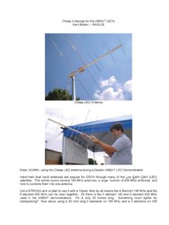
2 We reserve the right to continuously improve the product performance, so this document may be not in full compliance with the AP you purchased. The latest version of this document will be available at our website: 1. Hardware and features ID Name A MyFlyDream AutoPilot B GPS C 100A Current Sensor (optional 50A) D Customized shielded cables for Camera/VideoTX E Cables for RC-RX F Jumper, and header for camera connector G USB-TTL cable for firmware update MFD AP has build-in 3-axis gyro, 3-axis Acceleration sensor, 3 axis digital compass and barometer. AP has two CPUs, one for the MFD attitude calculation, the other in charge for the OSD and fly logic control. Base on this advanced hardware, AP can be used to control your plane to fly according the way points you defined, or to control the plane return to home automaticlly.
3 MFD AP s advanced features includes: 1) Full attitude AHRS, max angular rate is 2000deg/s. 2) Pixel based black/white OSD. High refresh rate to reduce the display latency. 3) Intergraded MFD Auto Antenna Tracker (AAT) support, can be used with MFD AAT (Automatic Antenna Tracker) directly. 4) All functions and parameters can be accessed with the OSD menu system. Especially users can define the waypoints with OSD visibly. 5) MAVLink protocol is supported. you can use APM Mission Planner (a 3rd open source GCS running on PC) to define waypoints or to trace the plane on the map in real time. There are also some apps running on mobile devices can be used with MFD AP. Specification COMMENT Weight 30g Power supply 7~20V (12V is recommended) Current consume <200ma@12V (with GPS, without other electronics) PWM input channels 6 (PWM input setup) or 8 (PPM input setup) PWM output channels 4 Maximum rolling angular 2000 degree/s Flight modes MANual, STaBlizer, CIRcle, ALTitude, WayPoinT, ReturnToHome MAX.
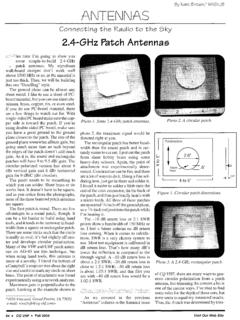
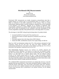
4 Waypoints 10 Support plane layouts Normal, Wing (Ailvator), V-Tail 2. Wiring * Please visit this link about wiring: The above picture shows AP s connection ports from A~J: Port Description A) Power power supply (Usually 12V) B) CH1~CH6 Input CH1~CH6 PWM inputs, connect to receiver C) CH1~CH4 Output CH1~CH4 PWM outputs to the servos D) GPS To GPS E) Data DataRadio (optional) F) Camera To camera G) AV-TX To video transmitter H) AUX Auxiliary port for AirSpeed sensor/Sonar .. etc. (optional) I) Sensors To current sensor board and RSSI signal J) EXT Extended port for future use Connect to the common devices as the picture shown below: A) Power This port supplies power to the AP. The AP has an internal 5V switching power unit so it can be powered from 7-20V. But the camera and the video transmitter will also share the power directly from this port.
5 Most of the camera and video TX need 12V, so we recommend you to power the AP with a 3S lipo (or use our DC-DC power module to get 12V power from your main battery). That will make the wiring easier and cleaner. Pins Use for A1 12V positive A2 Ground (negative) B) CH1~CH6 Input Connect RC receiver to this port to the read the RC control input. As showed in the picture, the WHITE pins are signal pins, RED pins are power supply pins to the receiver (these red pins are internally connected), and the BLACK pins are GND (these black pins are also internally connected). These 6 RED pins are isolated with the AP. AP does not supply power to these pins neither getting power from them. CH1~CH6 channel connection CH1 AIL CH2 ELE CH3 THR CH4 RUD CH5 Mode switch A (2-positions). In PPM mode it's for FUTABA PPM input CH6 Mode switch B (3-postions). In PPM mode it's for JR PPM input.
6 AP needs a 2-positions and a 3-positions switch to switch the flight modes. Please connect them to CH5 and CH6 as the above table. AP needs all these input channels to access all its functions. Especially you need to ensure all 6 channels are connected even you don't need CH4(RUD) for a flying wing. Use a receiver with PPM (PulsePositionModulation) output AP supports PPM signal input. If your receiver outputs PPM, only one cable is needed to connect your receiver to the AP. A) For Futaba (or similar) receivers, the definition of PPM channels for channel 1-4 are AIL, ELE, THR, and RUD. In this case please connect PPM cable to CH5. B) For JR (or similar) receivers, the definition for channel 1-4 are THR, AIL, ELE, and RUD. In this case please connect PPM cable to CH6. Once a valid PPM signal is recognized on CH5 or CH6, Input channels CH1~CH4 will automatically be used as auxiliary servo output ports.
7 AP will not accept PWM signals until it is power on again. C) CH1~CH4 Output Connect servos to this port so that AP is able to control your plane. WHITE pins are signal pins, RED pins are servo power supply, BLACK pins are GND. These red pins are internal connected with the red pins of PORT B (CH1~CH6 input port). NOTE : AP will not supply power to your servos or receiver. You need a 5V/6V BEC or something like that to supply power to your servos and receiver. CH1~CH4 output functions Channel Use for CH1 AIL servo output CH2 ELE servo output CH3 THR ESC output CH4 RUD servo output D) GPS Connect the GPS to this port. This port is also used for firmware update. Pins Function D1 TX D2 RX (connect to the GPS TX wire) . D3 power supply to the GPS D4 Ground E) Data This port is used for the telemetry data radio (or USB-TTL cable/Bluetooth ) You need this port if you want to upload waypoints from you ground station software.
8 Pins Use for E1 TX (to the telemetry radio RX) E2 RX (to the telemetry radio TX) E3 5V power (Can be adjusted to by a solder jumper inside the AP) E4 Ground F) Camera Connect your camera to this port. Use the power supply pin of this port (F2) ONLY if your camera can use the same voltage as you power the AP (usually 12V). For example your camera needs 12V power supply. And you also use 12V to power AP, just simply connect the 3 wires of the camera to this port in this case. If it is a 5V camera, you need to find other ways to supply 5V power to it separately and not to use the F2 pin. Pins Use for F1 GND Ground F2 PWR Power (the same voltage as the AP Power input pin -- A1) F3 VID (Camera video signal) G) AV-TX Connect your video transmitter to this port. Pins Use for G1 GND, Ground G2 PWR, power (voltage is the same as A1 pin of the AP) G3 VID, video output with the OSD information to the video TX.
9 G4 AUD, Audio output for the AAT tracker. Connect to the audio channel of the VideoTX Similar as PORT F (the camera port), if your video transmitter power supply voltage is different from the AP, you have to power the video TX separately and not to use the G2 PIN. H) AUX This port is used to connect with AUX devices. The AUX device may be a ultrasonic sensor or other stuffs. Usually we plug an AirSpeed sensor to this port. Just leave it alone if you don t need to use it yet. Pins Use for H1 Depends on the AUX device. (RXD for AirSpeed sensor) H2 Depends on the AUX device. H3 5V H4 GND I) Sensors These pins are for current sensor and RSSI input. Connect the current sensor comes with the AP directly to this port. The current sensor has a 4pin connector. Please align its black wire to I5 (GND pin). WARNING: Please solder 2 GND wire on the current sensor as close as possible to avoid burning the GND trace of the current sensor.
10 Because the trace on PCB is not able to handle 20A or higher current without enhancing with solder. After connecting the current sensor, the L1 (for RSSI input) is still available. Connect the RSSI signal from your RX to here if RSSI signal of the RX is available. The RSSI input is buffered inside the AP. So it s no need to use any external circuit to buffer your RSSI signal again. Pins Use for L1 RSSI (0~5V) L2 VOLT power pack (0~27V) L3 CURR power current (0~100A) or (0~50A) L4 PWR 5V L5 GND Ground J) EXT This is I2C extension port is for other devices. Pins Use for J1 SCL J2 SDA J3 PWR v J4 GND 3. Install and setup For better performance please mount the AP around the CG point of the plane. For small electrical plane there is no need to use any dumping material to mount the AP. Use the double sides tape or Velcro to mount the AP directly to the place would be fine for most cases.