Transcription of 2.4-GHz Patch Antennas - N5DUX
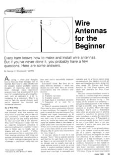
1 By Kent Britain," WA5 VJB Connecting the Radio to the Sky Patch Antennas Ghis time I'm going to show you / some simple-to- build i! Patch Antennas . My styrofoam wall-board designs don't work well above 1500 MHz or so, as the material is just too thick. Thus, we will be building this one "DeadBug" style. The ground plane can be almost any sheet metal. I like to use a sheet of PC- board material, but you can use sheet alu- minum, brass, copper, tin, or even steel. If you do use PC-board material, there are a few things to watch out for. With single-sided PC board make sure the cop- per side is toward the Patch . If you're using double-sided PC board, make sure you have a good ground to the ground plane closest to the Patch . The size of the ground plane somewhat affects gain, but going much more than an inch beyond the edges of the Patch doesn't add much gain.
2 As it is, the round and rectangular patches will have 9 to dBi gain. The circular-polarized version has about 6 dBi vertical gain and 6 dBi horizontal gain for 9 dBiC (dbi circular). The Patch needs to be something to which you can solder. Sheet brass or tin works best. It doesn't have to be square, and as you notice from the photographs, none of the three featured Patch Antennas are square. The first Patch is round. There are few advantages to a round Patch , though. It can be a bit harder to build using hand tools, and it tends to be narrower in band- width than a square or rectangular Patch . There are some tricks such that the circle is really an oval; it's fed slightly off cen- ter and develops circular polarization. Many of the VHF and UHF Patch anten- nas on AO-40 use this technique, but when using hand tools, this antenna is more of a novelty.
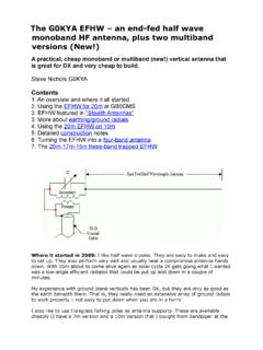
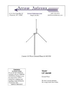
3 I found the bottom of a Campbell's soup can was about the right size and used it to markmy circle on sheet brass. The point of attachment was found experimentally using a network analyzer. Maximum gain is perpendicular to the Patch . Looking at the example shown in *I626 Vineyard, Grand Prairie, TX 75052 e-mail: <wa5vjb@ cq-vhcconz> - - Photo 1. Some Patch Antennas . photo 2, the maximum signal would be directed right at you. The rectangular Patch has better band- width than the round Patch and is cer- tainly easier to cut out. I just cut the Patch from sheet hobby brass using some heavy-duty scissors. Again, the point of attachment was experimentally deter- mined. Construction can be fun, and there are a lot of ways to do it. Using a fine sol- dering iron, just get in there and solder it.
4 I found it easier to solder a blob onto the end of the coax connector, tin the back of the Patch , and thenjust briefly heat it with a micro torch. All three of these patches are mounted l/4 inch off the ground plane, so a l14-inch rod positions the Patch while I'm heating it. The -10 dB return loss or 2:l SWR points show a bandwidth of 150 MHz or so. I feel a future column on dB return loss coming. When it comes to calcula- tions, SWR is a very clumsy system to use. Most test equipment is calibrated in dB return loss. That's how many dB's lower the reflection is compared to the through signal. A -10 dB return loss is about a 2:1 SWR; -20 dB return loss is close to : 1 SWR; -30 dB return loss is about :l SWR; and that flirt you see with -40 dB return loss would be a : 1 SWR.
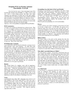
5 As we covered in the previous " Antennas " column in the Summer issue Photo 2. A circular Patch . - Polarization 0 Attach I - I- 4 to 5" Figure 1. Circular Patch dimensions. Photo 3. A rectangular Patch . of CQ VHF, there are many ways to gen- erate circular polarization from a Patch antenna , but trimming the corners a bit is one of the easiest ways. I've tried to find some rules for the depth of those cuts, but none seem to equal my measured results. Thus, the .6 inch was determined by trim- 64 . CQ VHF . Fall 2004 Visit Our Web Site Photo 4. Construction of the Patch . Photo 5. Construction of the Patch . ming, trimming, and trimming a little at a time until the gain didn't change as I rotated the Patch 90 degrees when pointed at the source antenna . First, the antenna can be mounted at the focus of a dish to give you more gain.
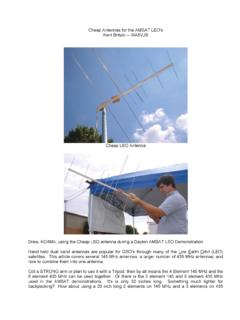
6 How much more gain? Well, that depends on a lot of factors, but an 18-inch dish, which is about the small- est size you would want to use on GHz, will give you about 15 dBi gain. A 3-foot dish would give 22 to 23 dBi of gain. Bigger? Okay, a 6-foot dish would give in the 29-30 dBi range. Just remember that when vou use a circular-uolarized anten- Figure 2. Rectangular Patch dimensions. - Polarization 0 Y d 0- - I- 4 to 5" na as a dish feed, the feed is bouncing the sigh off the dish. Therefore, the world is seeing a mirror image of the feed. If you want a right-hand circular-polarized dish, you need to install a left-hand feed. This feed will work great with OSCAR AO-51 or almost any S-Band bird. vq ". El - This antenna also makes a good little antenna for your Wi- Fi experiments.
7 Like the AMSAT version, it can be mounted at the focus of a dish if you are working on a really long shot. (I have heard of one lad pointing one of these at a local motel for internet access, but I can't condone such actions!) &]$e~ts~ D-efi?e \jYre Ge', Lg[-p?s From Jeff we received some questions on tweaking Cheap Yagis and similar Antennas . First, make sure the coax is attached correctly. At the Central States VHF Society antenna range last July, I saw a Cheap Yagi with the coax reversed. The coax shield was to the tip of the "J" and the center conductor was to the middle of the element. This person had noticed that the coax was hot, so he put a long string of ferrite beads on the coax. This did keep RF off the coax, and the antenna performed up to spec on the antenna range.
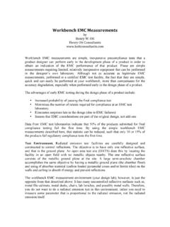
8 Frankly, that's not something I would have expected. However, it's a lot easier if you connect the coax per my diagrams. Next, trim the free end of the "J" for best SWR. This is much like trimming or adjusting the driven element of any Yagi. Last, I have my own "Yagi Tweaker," which I've shown before (see photo 10). Short pieces of Yagi element material Photo 6. Rectarzgular Patch frequency response. are taped toihe ends of a wood stick. putting the tweaker near Photo 7. A circular-polarized Patch . Fa11 2004 CQ VHF 65 RHCP Polarization LPCP Polarization Attach Point Point Figure 4. Left- and right-hand circular-polarized notches. Photo 8. Circular-polarized Patch frequency response. - RHCP Polarization " m 0 Y d- 0- .4 - L4t~5" Figure 3. Circular-polarized Patch dinzensions.
9 Photo 9. The author's "Yagi Tweaker. " the tips of each element quickly shows you the most sensitive elements. If the SWR starts going up as the tweaker gets near the tip of the element, then the ele- ment is too long. If the SWR dips as you get the tweaker near the tip of the ele- ment, then it's too short. This really needs to be done on an anten- na range. Retuning a Yagi for a super-flat SWR destroys its pattern, and that's not the sweep and the shutter to almost sync going to get you anywhere. However, a is the hardest part. It takes about ten shots slightly long director #1 is the quickest to have one come out, so until I get my way to kill the SWR of a Cheap Yagi. $100K analyzer, you'll have to suffer through my camera shortcomings. -- Have fun with Antennas , and we'll see Photographing a good old analog net- what makes it out of my lab for the next work analyzer CRT is fun (not).
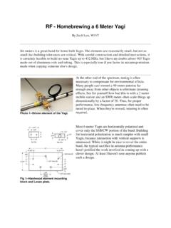
10 Getting " Antennas " column. A Fun antenna Last July at the Central States VHF Society antenna contest, Bob, VE3 BFM, showed up with this interesting 900-MHz antenna made out of AOL CDs. Not bad! It measured right at 10 dBi gain! The design is known as a "Disk and Rod" or sometimes a "Cigar" antenna . Bob found that a straight CD resonates at about 850 MHz, so he used one as a Yagi reflector. The other CDs had been trimmed down in diameter somewhat so they could act as Yagi directors. I think I've figured out how to model one of these around a Cheap Yagi driven element, so we just might have a fun project in the near future if I can come up with an easy way of cutting down the diameter of a CD. That brings up the question of the antenna gain of music vs. data CDs.