Transcription of Balun Designs for Wireless, - N5DUX
1 Balun Designs for wireless , .. Mixers, Amplifiers and Antennas BalunsJind wide use in mixer, antenna and balanced amplzJier circuits, yet their design is not widely practiced. The author shows a variety of Designs , that are simple and yield goodfirst pass results. Rick Sturdivant Hughes Aircraft Company El Segundo, California aluns find wide use in mixer, antenna and bal- anced amplifiercircuits. Yet Balun design is still regarded as if it were black magic by many engineers, partly due to the fact that practical design information on baluns can be difficult to find. How- ever, many good baluns have been developed over the years and somc are surprisingly simple to design . In this paper we will review somc good Balun Designs and show that good first pass design results can be obtained. Balun circuits find wide application especially in new wireless applications as they have customarily in RF and microwave circuits.
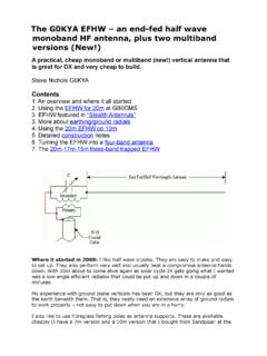
2 They are used in circuits such as mixers, push-pull amplifiers, antennas and other applications requiring a conversion between unbal- anced transmission line (such as coax, stripline or microstrip) and a balanced line (such as a two wire transmission line of the type used for old television antenna leads). A properly designed Balun is essential for these types of circuits. In fact, it is often the performance of the Balun which predominately determines the perfonnance of the overall circuit. 34 AYPL~~~ MICROWAVE Sltnirn~t. 1993 Interestingly, the design of baluns is rarely covered in most engineeringcurriculum. Furthermore, the design information on them is scattered throughout a number of different articles. The goal of this paper is to save the circuit designer time by cataloging a few good Balun Designs . strip Balun Theory housing dielectric support ~h~ purpose of a halull is to forln a good transition Figure 2.
3 Shielded parallel plate line is a balanced transmission line. from an unbalanced transmission line into a balanced transmission line. Figure 1 illustrates coax, a familiar unbalanced line. The current I, exists on the center conductor, I, is the ground return for I,, and Ie is the external current induced on the outside of the shield. The shield is considered tied to earth ground at the input. A shielded parallel plate line, on the other hand, has equal potential and 180 degrees of phase difference between the current on the two conductors. with no current on the ground shield. This is illustrated in Figure 2. The currents are I,=-I,, and I, is the ground return. I, exists only when the eclual amplitude and opposite phasc relationship between I, and I, is not maintained. Ic is thc induced external current on ihe outside of the shield. To speak of the potential at the balanced end of thc circuit referenced to gro~lnd is unnecessary, since it is the potential between the balanced pair of co~lductors which is responsible for the transmission of power along fact, for the theoretically perfect Balun , an ideal current source placed between one of the balanced lines and ground will produce zero current in that line.
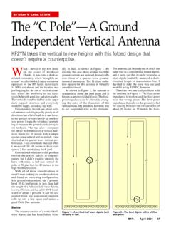
4 However, for many mixer and amplifier Designs it is not necessary to have a theoretically perfect Balun . That is, many circuits do not require the infinite ground isolation property of the ideal Balun . Rather, these circuits only require that the voltages on the balanced lines are of equal magnitude and opposite phase, and that the impedance to ground may be finite (but equal for both conductors). Baluns have been developed over the years which meet this requirement. These quasi baluns are the major focus of this article. Half Wave Tran, Line Possibly the simplest Balun is shown in Figure 3. The phase shift of 180 degrees which is required for Balun operation is achieved by a half wavelength piece of transmission line. Impedance tnatchingcan be achieved by properly choosing the impedance of the halfwave line. This is an inherently narrow band design . A quarter wave transformer can be added at the unbal- anced input to improve theperfom~ance.
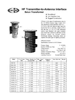
5 This circuit is designed by modifying the line impedance of the half wave and quarter wave line (if used) to achieve the best performance. unbalanced =--+ e end view side view Figure I. Coaxial line is an unbalanced transmission line. Figure 3. Simple half wavelength Balun . 36 APPLIED MICROWAVE S~rrnrnr~. 1993 N Sections of Halj" Wave Lines Lumped Element Balun By interconnecting anusnber of halfwavelength trans- mission lines with quarter wavelength lines (Figure 41, wide band baluns are possiblc[l]. The bandwidth can be i~lcrcascci by adding more sections. The order, n, of the Balun depends upon the nurnber of halfwavelength sections. The half wavelength lines provide the 180 degrees of phase shift while the quartel- wavelength lines give the impedance transformations. This is a Balun design that is practical in tnicrostrip. Due to its planar structure the circuit pattern can beetchedon only one side of the substrate.)
6 Balanced output Figure 4. N section halfwave Balun . An n=2 form of this Balun has bccn dcsiglied and tested. The cleinent lengths and isnpedances have been optimized. The measured performance is shown in Figure 5. Return Loss -4-- Isotat~on lnsertlon Loss lnse~tlon Loss Baluns can be doigncd by using lu~nped elemenh. Lumpcd clement baluns are well suited for low frc- quency and MMIC applications[2],[3] for which dis- tributed linc lengths would be too bulky. The theory of lusnped clesne~lt baluns i5 based upon the familiar rat race ring hybrid. The distributecl transini\\ion line4 of the rat race ring are replaced by lu~npedelement equiva- lent circuits. The quarter wave length lines of the ratrace ring are replaced by lumped element lowpa5s f~lter networks. The three quarter wavelength line is replaced by a highpaus filter network. The resultant equivalent lumped element circuit is shown in Figure 6.
7 The required design equations arc included. where: oL = I/(oC) = 1 4K R = Port Impedance w = center frequency (rad/sec) Figure 6. Lumped element Balun . 'The theoretical pel-forniance of this Balun is shown in Figure 7. A 50 ohm load was assunled on all ports. Therefore, C = and L = Parallel Plate Balun Of all the baluns in use today possibly the most widely used is the quarter wave coupled line Balun . There are many configurations for it. The broadside coupled parallel plate Balun is very common[4] ,[5],[6]. It is 6 7 a 9 10 11 Sound in Inany mixel- Designs and is shown in Figure 8. Frequency [GHZJ It consists of an input rnicrostrip line which transitions into parallel plate line. The parallel plateline is adoublc Figure 5. Measured performance of n=2 half wave Balun . sided substrate. 38 APPl,lb,L> MICROWAVE Sr~t)it~ic>/. 1993 Return Loss .. Insert on Loss Lsolatlon -------- Insertlot1 Loss a magnetic wall 15 placed between the balanced lincs.]
8 Their neth hod, which i\ bawd on the variational tech- nique, is 5traight forward and easy to program. 7 8 9 10 11 12 13 Frequency [GHz] Figure 7. Theoretical performanceofthe lumped element Balun . Figure 8. Parallel plate Balun . Backside contluctor shown as dashed lines, topside conductors as solid lines. A taper is usually added to the backside gro~uid plane to aid in the modc conversion from microstrip to parallel platc. However, relatively good performance is possible without using a taper ifthe eve11 mode impedance is very large cornpared to the odd mode impedance. Usually soft substrates a]-e useci for the support dielectric and are usually very thin (5mil typically). A side view of the Balun is shown in Fiprc 9. The parallel platc region is actually a pair of coupled lines. Thc even and odd ~nodc analysis; can be done using the tcchniyue devclopcd by Bhat andKo~11[7] Costhe analy- sis of broadside co~~pled suspended s~~bstrate stripline (BCSSS).
9 The odd impedance, Zoo. is the characteristic impedance ofone of the baliunced conductors to ground when a shorting plane is placed at the symmetry line between the balanced conductors. Thc even mode in- pedance is the characteristic irnpcd~itlce ~ne~zsi~red bc- tween one of the balanced conductors and ground when One of the benefits of the parallel platc Balun is that it is possible to achleve grouncl isolation at the balanced outputs. That is the balancccl lincs have their potential refcrcnccd to each other, with near Lero potential be- tween either balanced linc and ground. Figure 9. Side view of the parallel plate Balun . 'I'lie actual parallel plate impedance(Zop) is twice the BCSSS odd mode impedance. Therefore, the impcd- ance u5edfor the design of the balunis rclatcd totheocid node BCSSS impedancc by WhereZop 1s the parallel platc impedance. In order to have a good match at the rnicrostrip input, we must have Equation 1.
10 Z<,(, = dK The parallel platc region of thc Balun is shown to be a quarter \\~avelcngtli long. Use the effective dielectric constant for the odd mode BCSSS to detcrminc this Icngth. The even modc iinpcda~lcc must be very large compared to the ocld n~odc inipcdance. As a~ninitnunl, This design method was used and the theoretical rc- sponx of the Balun is shown in Figure 10. It used Zoo = 35 oh111 and Zoe = 350 ohm. As can be seen, the power split is not thc desired 3dB. However, as the cven mode impcdance increases relative to the odd mode imped- ance, the power split approaches the desired 3dB. 5 6 7 8 9 10 11 Frequency [GHz] Figure 10. Frequency response of the parallel plate Balun . A parallel plate Balun was used in the design of amixer realized on 25 mil alumina (er= ). The performance is good for a first cut design . The design called for a mixer with a bandwidth covering 8-10 GHz with less than 9dB conversion loss.)