Transcription of A Single-Supply Op-Amp Circuit Collection
1 Application ReportSLOA058 November 20001A Single-Supply Op-Amp Circuit CollectionBruce CarterOp-Amp Applications, High Performance Linear ProductsOne of the biggest problems for designers of Op-Amp circuitry arises when the Circuit mustbe operated from a single supply , rather than 15 V. This application note providesworking Circuit supply vs single Op-Amp Resistor and Capacitor Pole Low Pass Filter High Pass Filter All-Pass Multiple Feedback (MFB)..16 Twin Akerberg-Mossberg State A Standard Resistor and Capacitor supply (L) vs single supply (R) Operation at Gain Inverting Attenuation With an Op Attenuation Single-Supply Op-Amp Circuit Collection7 Inverting Summing Inductor Instrumentation-Amplifier Instrumentation-Amplifier Circuit With Only Two Op Filter Filter Filter Low- and High-Pass Filter Op-Amp Twin-T Filter in Band-Pass Op-Amp Twin-T Filter in Notch Twin-T Low-Pass Twin-T High-Pass Twin-T Notch Fliege Fliege Fliege Fliege Low-Pass High-Pass Band-Pass Notch Low-Pass and Band-Pass Four- Op-Amp Single-Supply Op-Amp Circuit Collection31 IntroductionThere have been many excellent collections of Op-Amp circuits in the past, but all of them focusexclusively on split- supply circuits.
2 Many times, the designer who has to operate a Circuit from asingle supply does not know how to do the operation requires a little more care than split- supply circuits. The designer shouldread and understand this introductory Split supply vs single SupplyAll op amps have two power pins. In most cases, they are labeled VCC+ and VCC-, but sometimesthey are labeled VCC and GND. This is an attempt on the part of the data sheet author tocategorize the part as a split- supply or Single-Supply part. However, it does not mean that the opamp has to be operated that way it may or may not be able to operate from different voltagerails. Consult the data sheet for the op amp, especially the absolute maximum ratings andvoltage-swing specifications, before operating at anything other than the recommendedpower- supply voltage(s).Most analog designers know how to use op amps with a split power supply .
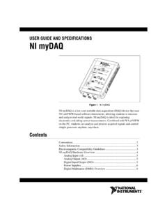
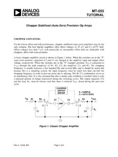
3 As shown in the lefthalf of Figure 1, a split power supply consists of a positive supply and an equal and oppositenegative supply . The most common values are 15 V, but 12 V and 5 V are also used. Theinput and output voltages are referenced to ground, and swing both positive and negative to alimit of VOM , the maximum peak-output voltage Single-Supply Circuit (right side of Figure 1) connects the Op-Amp power pins to a positivevoltage and ground. The positive voltage is connected to VCC+, and ground is connected to VCC-or GND. A virtual ground, halfway between the positive supply voltage and ground, is thereference for the input and output voltages. The voltage swings above and below this virtualground to the limit of VOM . Some newer op amps have different high- and low-voltage rails,which are specified in data sheets as VOH and VOL, respectively.
4 It is important to note that thereare very few cases when the designer has the liberty to reference the input and output to thevirtual ground. In most cases, the input and output will be referenced to system ground, and thedesigner must use decoupling capacitors to isolate the dc potential of the virtual ground from theinput and output (see section ).- supply -++ supply +SUPPLYHALF_SUPPLY-+ Figure 1. Split supply (L) vs single supply (R) CircuitsA common value for single supplies is 5 V, but voltage rails are getting lower, with 3 V and evenlower voltages becoming common. Because of this, Single-Supply op amps are often rail-to-raildevices, which avoids losing dynamic range. Rail-to-rail may or may not apply to both the inputand output stages. Be aware that even though a device might be specified as rail-to-rail, someSLOA0584A Single-Supply Op-Amp Circuit Collectionspecifications can degrade close to the rails.
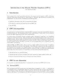
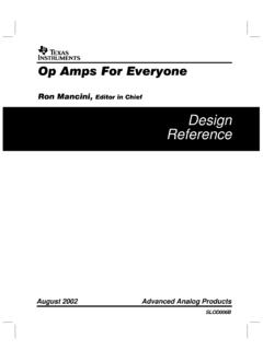
5 Be sure to consult the data sheet for completespecifications on both the inputs and outputs. It is the designer s obligation to ensure that thevoltage rails of the op amp do not degrade the system Virtual GroundSingle- supply operation requires the generation of a virtual ground, usually at a voltage equal toVcc/2. The Circuit in Figure 2 can be used to generate Vcc/2, but its performance deteriorates atlow k +Vcc+VccR2100 k -+ F Figure 2. Single-Supply Operation at VCC/2R1 and R2 are equal values, selected with power consumption vs allowable noise in C1 forms a low-pass filter to eliminate conducted noise on the voltage rail. Someapplications can omit the buffer op what follows, there are a few circuits in which a virtual ground has to be introduced with tworesistors within the Circuit because one virtual ground is not suitable.
6 In these instances, theresistors should be 100 kW or greater; when such a case arises, values are indicated on AC-CouplingA virtual ground is at a dc level above system ground; in effect, a small, local-ground system hasbeen created within the Op-Amp stage. However, there is a potential problem: the input sourceand output load are probably referenced to system ground, and if the Op-Amp stage is connectedto a source that is referenced to ground instead of virtual ground, there will be an unacceptabledc offset. If this happens, the op amp becomes unable to operate on the input signal, because itmust then process signals at and below its input and output solution is to ac-couple the signals to and from the Op-Amp stage. In this way, the input andoutput devices can be referenced to ground, and the Op-Amp circuitry can be referenced to avirtual more than one Op-Amp stage is used, interstage decoupling capacitors might becomeunnecessary if all of the following conditions are met: The first stage is referenced to virtual ground.
7 The second stage is referenced to virtual Single-Supply Op-Amp Circuit Collection5 There is no gain in either stage. Any dc offset in either stage is multiplied by the gain inboth, and probably takes the Circuit out of its normal operating there is any doubt, assemble a prototype including ac-coupling capacitors, then remove themone at a time. Unless the input or output are referenced to virtual ground, there must be aninput-decoupling capacitor to decouple the source and an output-decoupling capacitor todecouple the load. A good troubleshooting technique for ac circuits is to terminate the input andoutput, then check the dc voltage at all Op-Amp inverting and noninverting inputs and at theop-amp outputs. All dc voltages should be very close to the virtual-ground value. If they are not,decoupling capacitors are mandatory in the previous stage (or something is wrong with thecircuit).
8 Combining Op-Amp StagesCombining Op-Amp stages to save money and board space is possible in some cases, but itoften leads to unavoidable interactions between filter response characteristics, offset voltages,noise, and other Circuit characteristics. The designer should always begin by prototypingseparate gain, offset, and filter stages, then combine them if possible after each individual circuitfunction has been verified. Unless otherwise specified, filter circuits included in this documentare unity Selecting Resistor and Capacitor ValuesThe designer who is new to analog design often wonders how to select component resistors be in the 1- decade or the 1-M decade? Resistor values in the 1-k to100-k range are good for general-purpose applications. High-speed applications usually useresistors in the 100- to 1-k decade, and they consume more power.
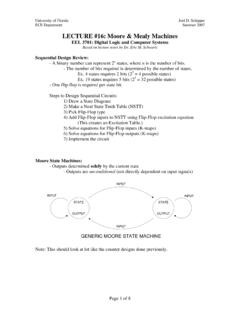
9 Portable applicationsusually use resistors in the 1-M or even 10-M decade, and they are more prone to formulas for selecting resistor and capacitor values for tuned circuits are given in thevarious figures. For filter applications, resistors should be chosen from 1% E-96 values (seeAppendix A). Once the resistor decade range has been selected, choose standard E-12 valuecapacitors. Some tuned circuits may require E-24 values, but they should be avoided wherepossible. Capacitors with only 5% tolerance should be avoided in critical tuned circuits use 1% Basic GainGain stages come in two basic varieties: inverting and noninverting. The ac-coupled version isshown in Figure 3. For ac circuits, inversion means an ac-phase shift of 180 . These circuitswork by taking advantage of the coupling capacitor, CIN, to prevent the Circuit from having dcgain.
10 They have ac gain only. If CIN is omitted in a dc system, dc gain must be taken is very important not to violate the bandwidth limit of the op amp at the highest frequency seenby the Circuit . Practical circuits can include gains of 100 (40 dB), but higher gains could causethe Circuit to oscillate unless special care is taken during PC board layout. It is better to cascadetwo or more equal-gain stages than to attempt high gain in a single Single-Supply Op-Amp Circuit CollectionVoutR3R2 Vcc/2 Gain = R2/R1R3 = R1||R2for minimum error dueto input bias currentINVERTINGR1+Vcc-+VinCin+VccR1 NONINVERTING+-VinR2 Gain = 1 + R2/R1 Input Impedance = R1||R2for minimum error dueto input bias currentVoutVcc/2 Cin Figure 3. AC-Coupled Gain AttenuationThe traditional way of doing inverting attenuation with an Op-Amp Circuit is shown in Figure 4, inVoutGain = R2/R1R3 = R1||R2for minimum error dueto input bias currentVinVcc/2R1R2+VccR3 Cin-+INVERTING Figure 4.