Transcription of A Truly Broadband, Efficient Low-Band Dipole
1 A Truly broadband , Efficient Low-Band Dipole The Search for Ham Radio's Holy Grail . By Douglas K. Smith, W7ZZ, and Terry Conboy, N6RY. Douglas K. Smith, W7ZZ. Email: My quest for the ham radio equivalent of the holy grail a Truly broadband 80 meter Dipole began in the spring of 2008, when I moved into my new QTH on five wooded acres in a semi-rural area. Finally free of restrictive covenants and neighbors who failed to see the beauty in amateur radio antennas, I dreamed of building, for the first time in my life, a reasonably competitive contest station. I eagerly looked forward to the contest mayhem on both phone and CW. The station of my dreams would have two freestanding towers, one for the run rig and everyday DXing, and one for the search and pounce second rig.
2 The tower for the run . station was to have a four element SteppIRTM, which would cover 20 through 6 meters, and a two element beam for 40 meters. For vertical polarization on 80 for the run rig, I designed and built a remotely tuned elevated ground plane that could be used anywhere in the band with an SWR very close to 1:1. A similarly designed, remotely tuned 160 meter inverted L ground plane was also erected. A horizontally polarized antenna would be needed for the run rig for good coverage on 80 meters, however, particularly for domestic contests such as the ARRL. Sweepstakes and the Washington State Salmon Run. The second tower was to have a tribander, but wires would be needed for both 80 and 40 for the S&P rig as well.
3 Since I intended to actively operate both phone and CW, both every day and in contests, I began to consider how I. could construct horizontally polarized wires for 80 and 40 that would have a very low SWR in both modes. While we own five acres, to maintain the pristine nature of the site and for maximum privacy, we had cleared only a relatively small area in the middle of the parcel for the house and yard (to include areas for the towers, where they would be somewhat hidden from the house). When it came time to lay out the low band dipoles , taking advantage of the tallest and most strategically located antenna trees for support, it surprisingly turned out that I did not have room for very many antennas (and that was before my XYL expressed her opinion on the subject!)
4 It became obvious that the few wires that I could put up were going to have to do double duty, working well in both the CW and phone subbands, and thus my search for ham radio's holy grail a Truly broadband , but Efficient , Dipole began. This article will chronicle my quest and the many valuable lessons that were learned along the way. The Challenge of Bandwidth How Serious A Problem Is It? Like most hams, I knew from reading texts and journals, and from practical experience, that antennas have a finite 2:1 SWR bandwidth and that, on the lower frequency bands, that bandwidth is probably not sufficient to allow satisfactory operation over the entire band .
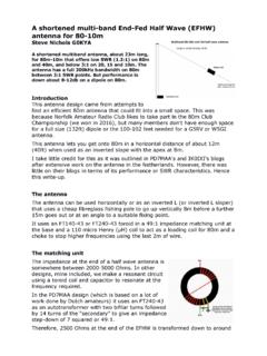
5 Beyond that general knowledge, I had not previously given much thought to the bandwidth problem, however. I had always done what most of us do: cut the Dipole using the formula we memorized to pass the license exam (LFeet = 468/FMHz), fed it directly with 50 ohm coaxial cable, hoisted it into the air as high as possible, pruned and tuned it as best as possible and then lived with the result, as unsatisfactory as that usually proved to be, especially on 80 meters. Figure 1 shows SWR plots for dipoles made and fed in that typical fashion for all the HF. bands, as modeled using EZNEC at three different heights above ground: 80, 60 and 35 feet.
6 These graphs vividly depict the bandwidth problem on the lower frequencies, with the results varying significantly with antenna height. A Truly broadband , Efficient Low band Dipole -1 - W7ZZ and N6RY, c. 2015. Fig 1. EZNEC models of dipoles from the standard formula, fed directly with 50 ohm coax (blue line) or series matched (purple line). For example, an 80 meter Dipole cut according to the formula, hung at 80 feet and directly fed with 50 ohm coax will exhibit a very poor best case SWR of :1 at resonance and has a 2:1 SWR bandwidth of a mere 125 kilohertz. Matching that typical Dipole , which has a predicted impedance of ohms, to the 50 ohm coax using a series match (discussed below).
7 A Truly broadband , Efficient Low band Dipole -2 - W7ZZ and N6RY, c. 2015. lowers the SWR at resonance to 1:1, but still the 2:1 SWR bandwidth is only 300 kilohertz just 60% of the band . The :1 bandwidth of the series matched antenna at 80 feet is 175 kilohertz, or a mere 35% of the band . To meet my goals, at least two such antennas, and preferably three, would be needed on 80 meters, if they were erected at 80 feet above ground. At 60 feet, the typical Dipole exhibits an SWR of at resonance and has a 2:1 SWR bandwidth of 150. kilohertz. Matching the 60 foot antenna to its actual impedance of ohms improves overall SWR but helps little with bandwidth.
8 2:1 SWR bandwidth is still only 250 kilohertz and 150. kilohertz for :1 bandwidth. At a height of thirty-five feet, the 80 meter Dipole constructed according to the classic formula and directly fed with 50 ohm coax exhibits a better SWR of :1 at resonance, but has a 2:1 bandwidth of about 150 kilohertz and a :1 bandwidth of only 100 kilohertz. Series matching the 35 foot high antenna barely affects its bandwidth at all. An 80 meter Dipole at that height is radiating most of its energy nearly straight up, so it is not an effective antenna for other than short range contacts, leaving aside how many such antennas it would take to cover the whole band satisfactorily.
9 The problem on 160 meters is even worse. While SWR at resonance is modeled to be at 35 feet and at 80 feet, 2:1 bandwidth is only 75 kilohertz or less at either height. On 40 meters, an unmatched antenna built in typical fashion is predicted to exhibit an SWR at resonance of at 35 feet in height and at 80 feet. A series matched 40 meter antenna at either 80 or 35 feet meets the 2:1 SWR bandwidth objective, but the goal of SWR at or below :1 across the whole band is not met if the antenna is erected at 80 feet. Series matched 20 and 15 meter dipoles at any height meet the :1 SWR goal across the band , with the plot on 15. meters being especially low across the band .
10 However, on 10 meters, the :1 SWR goal is not met by a series matched Dipole at any height. These EZNEC plots lead to the conclusion that the need for a broadband design is limited primarily to the lower frequency bands: 40, 80 and 160. meters, although there may be room for improvement on 20 and especially 10 meters, as well. This preliminary modeling was instructive in two respects. First, I learned why all those dipoles that I had tried to prune and tune over the years had not worked very well, often with poor SWR even at their point of resonance. When I was successful in getting the antennas fairly high up in the air, their feed point impedance was far from 50 ohms, with resulting high SWR.