Transcription of AC Generators - EandM
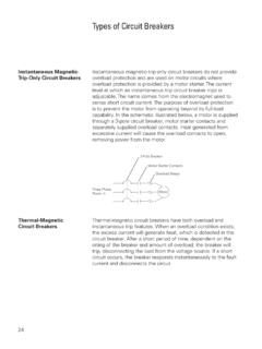
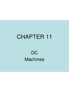
1 44AC GeneratorsBasic Generator A basic generator consists of a magnetic field, an armature , slip rings, brushes and a resistive load. The magnetic field is usually an electromagnet. An armature is any number of conductive wires wound in loops which rotates through the magnetic field. For simplicity, one loop is shown. When a conductor is moved through a magnetic field, a voltage is induced in the conductor. As the armature rotates through the magnetic field, a voltage is generated in the armature which causes current to flow. Slip rings are attached to the armature and rotate with it. Carbon brushes ride against the slip rings to conduct current from the armature to a resistive PieceMagnetic FieldArmatureBrushSlip RingR1 Basic Generator Operation An armature rotates through the magnetic field. At an initial position of zero degrees, the armature conductors are moving parallel to the magnetic field and not cutting through any magnetic lines of flux.
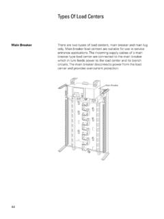
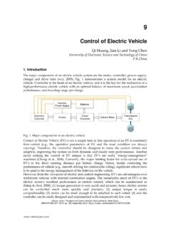
2 No voltage is induced. R145 Generator Operation from The armature rotates from zero to 90 degrees. The conductors Zero to 90 Degrees cut through more and more lines of flux, building up to a maximum induced voltage in the positive Operation from The armature continues to rotate from 90 to 180 degrees, 90 to 180 Degrees cutting less lines of flux. The induced voltage decreases from a maximum positive value to Operation from The armature continues to rotate from 180 degrees to 270 degrees. The conductors cut more and more lines of flux, but in the opposite direction. voltage is induced in the negative direction building up to a maximum at 270 Operation from The armature continues to rotate from 270 to 360 degrees. 270 to 360 Degrees Induced voltage decreases from a maximum negative value to zero. This completes one cycle. The armature will continue to rotate at a constant speed.
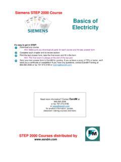
3 The cycle will continuously repeat as long as the armature Revolution360 Degrees47 FrequencyThe number of cycles per second made by voltage induced in the armature is the frequency of the generator. If the armature rotates at a speed of 60 revolutions per second, the generated voltage will be 60 cycles per second. The accepted term for cycles per second is hertz. The standard frequency in the United States is 60 hertz. The following illustration shows 15 cycles in 1/4 second which is equivalent to 60 cycles in one SecondFour-Pole AC Generator The frequency is the same as the number of rotations per second if the magnetic field is produced by only two poles. An increase in the number of poles, would cause an increase in the number of cycles completed in a revolution. A two-pole generator would complete one cycle per revolution and a four-pole generator would complete two cycles per revolution.
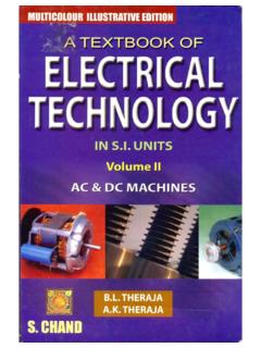
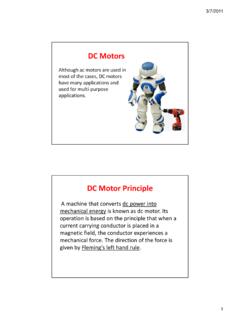
4 An AC generator produces one cycle per revolution for each pair of Revolution48 Voltage and CurrentPeak Value The sine wave illustrates how voltage and current in an AC circuit rises and falls with time. The peak value of a sine wave occurs twice each cycle, once at the positive maximum value and once at the negative maximum ValuePeak ValueTime+0-Peak-to-Peak Value The value of the voltage or current between the peak positive and peak negative values is called the peak-to-peak +0-Instantaneous Value The instantaneous value is the value at any one particular time. It can be in the range of anywhere from zero to the peak value.+0-TimeInstantaneous Value49 Calculating Instantaneous The voltage waveform produced as the armature rotates Voltage through 360 degrees rotation is called a sine wave because instantaneous voltage is related to the trigonometric function called sine (sin = sine of the angle).
5 The sine curve represents a graph of the following equation:e = Epeak x sin Instantaneous voltage is equal to the peak voltage times the sine of the angle of the generator armature . The sine value is obtained from trigonometric tables. The following table reflects a few angles and their sine value. AngleAngleSin Sin30 Degrees60 Degrees90 Degrees120 Degrees150 Degrees180 Degrees210 Degrees240 Degrees270 Degrees300 Degrees330 Degrees360 following example illustrates instantaneous values at 90, 150, and 240 degrees. The peak voltage is equal to 100 volts. By substituting the sine at the instantaneous angle value, the instantaneous voltage can be = +100 Volts150 = +50 Volts240 = Volts+0-Any instantaneous value can be calculated. For example:240 e = 100 x = volts50 Effective Value of an Alternating voltage and current are constantly changing Sine Wave A method of translating the varying values into an equivalent constant value is needed.
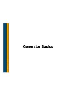
6 The effective value of voltage and current is the common method of expressing the value of AC. This is also known as the RMS (root-mean-square) value. If the voltage in the average home is said to be 120 volts, this is the RMS value. The effective value figures out to be times the peak Vpeak x = 120 VrmsPeak Volts+0-The effective value of AC is defined in terms of an equivalent heating effect when compared to DC. One RMS ampere of current flowing through a resistance will produce heat at the same rate as a DC ampere. For purpose of circuit design, the peak value may also be needed. For example, insulation must be designed to withstand the peak value, not just the effective value. It may be that only the effective value is known. To calculate the peak value, multiply the effective value by For example, if the effective value is 100 volts, the peak value is 141 71.
7 The graphic representation of AC voltage or current values over a period of time is a _____ _____ .2. Each phase of three phase AC power is offset by _____ An AC generator produces _____ cycle per revolution for each pair of What is the instantaneous voltage at 240 degrees for a peak voltage of 150 volts?5. What is the effective voltage for a peak voltage of 150 volts?51 InductanceThe circuits studied to this point have been resistive. Resistance and voltage are not the only circuit properties that effect current flow, however. Inductance is the property of an electric circuit that opposes any change in electric current. Resistance opposes current flow, inductance opposes change in current flow. Inductance is designated by the letter L .. The unit of measurement for inductance is the henry (h).Current Flow and Current flow produces a magnetic field in a conductor.
8 The Field Strength amount of current determines the strength of the magnetic field. As current flow increases, field strength increases, and as current flow decreases, field strength DegreesNo Current30 DegreesIncreasingCurrent90 DegreesMaximumCurrentAny change in current causes a corresponding change in the magnetic field surrounding the conductor. Current is constant in DC, except when the circuit is turned on and off, or when there is a load change. Current is constantly changing in AC, so inductance is a continual factor. A change in the magnetic field surrounding the conductor induces a voltage in the conductor. This self-induced voltage opposes the change in current. This is known as counter emf. This opposition causes a delay in the time it takes current to attain its new steady value. If current increases, inductance tries to hold it down. If current decreases, inductance tries to hold it up.
9 Inductance is somewhat like mechanical inertia which must be overcome to get a mechanical object moving or to stop a mechanical object from moving. A vehicle, for example, takes a few moments to accelerate to a desired speed, or decelerate to a stop. 52 Inductors Inductance is usually indicated symbolically on an electrical drawing by one of two ways. A curled line or a filled rectangle can be are coils of wire. They may be wrapped around a core. The inductance of a coil is determined by the number of turns in the coil, the spacing between the turns, the coil diameter, the core material, the number of layers of windings, the type of winding, and the shape of the coil. Examples of inductors are transformers, chokes, and Inductive Circuit In a resistive circuit, current change is considered instantaneous. If an inductor is used, the current does not change as quickly.
10 In the following circuit, initially the switch is open and there is no current flow. When the switch is closed, current will rise rapidly at first, then more slowly as the maximum value is approached. For the purpose of explanation, a DC circuit is used.+_L1R1 Inductive Time Constant The time required for the current to rise to its maximum value is determined by the ratio of inductance (in henrys) to resistance (in ohms). This ratio is called the time constant of the inductive circuit. A time constant is the time (in seconds) required for the circuit current to rise to of its maximum value. When the switch is closed in the previous circuit, current will begin to flow. During the first time constant current rises to of its maximum value. During the second time constant, current rises to of the remaining , or a total of It takes about five time constants for current to reach its maximum value.