Transcription of AC Output DIN Rail Mount SSRs DR22 Series - Crydom
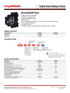
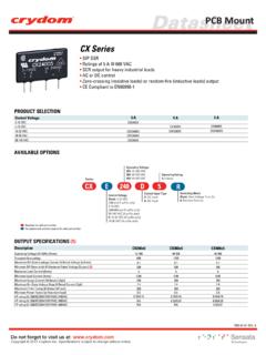
1 DR22 Series AC Output DIN rail Mount ssrs Output ratings up to 35 Amps at 600 VAC Built-in overvoltage protection Relay or Contactor configuration Integral heat sink eliminates the need for complex thermal calculations DBC substrate for superior thermal performance "Elevator" screw option to allow the use of ring or lug type terminals IP20 touch-safe housing AC or DC control C-UL-US and TUV approvedPRODUCT SELECTIONC ontrol Voltage20A 90-280 VAC/VDC DR2260A20x4-32 VDCDR2260D20x30A DR2260A30xDR2260D30x35A DR2260A35xDR2260D35xAVAILABLE OPTIONSR equired for valid part numberFor options only and not required for valid part numberOperating Voltage60: 48-600 VACS witching TypeBlank: Zero Voltage Turn-OnR: Instantaneous Turn-On (Motor Rating Certified)Control Voltage (1)A: 90-280 VAC/VDCD: 4-32 VDCS eriesDR2260A RRated Load Current20: 20 Amps30: 30 Amps35: 35 Amps [High I2t]UTerminal LayoutU: Relay ConfigurationV: Contactor Configuration (std.)
2 Screw)W: Contactor Configuration (elevator screw)Input ConnectorBlank: Screw TerminalJ: Spring Terminal (V and W suffixes only)V20 JOUTPUT SPECIFICATIONS(2)Description30 AOperating Voltage (47-440Hz) [VRMS]48-600 Transient Overvoltage [Vpk] (3)1200 Maximum Off-State Leakage Current @ Rated Voltage [mARMS]1 Minimum Off-State dV/dt @ Maximum Rated Voltage [V/ sec]500 Load Current, General Use UL508/LC A IEC62314 @ 40 C [ARMS] 30 Minimum Load Current [mARMS]100 Maximum 1 Cycle Surge Current (50/60Hz) [Apk]716/750 Maximum On-State Voltage Drop @ Rated Current [Vpk] 1/2 Cycle I t for Fusing (50/60Hz) [A sec]2563/234335A20A48-60048-600120012001 15005002035 Load Current, Motor Starting UL508 FLA/LC B IEC62314 @ 40 C [ARMS] 14 Power Factor (at Maximum Load) (4) Rating UL 508/IEC62314 [HP (kW)]: 120 VAC1 ( ) ( )2 ( )Motor Rating UL 508/IEC62314 [HP (kW)]: 240 VAC 3 ( ) ( )5 ( )Motor Rating UL 508/IEC62314 [HP (kW)]: 480 VAC5 ( )3 ( )10 ( )INPUT SPECIFICATIONS(2)DescriptionDR2260 AxxxControl Voltage Range90-280 VAC/VDCM aximum Reverse Voltage-Minimum Turn-On Voltage 90 VAC/VDCMust Turn-Off Voltage 5 VAC/VDCM inimum Input Current (for on-state) 6 mA Maximum Input Current 10 mANominal Input Impedance Current LimitedMaximum Turn-On Time [msec]20 Maximum Turn-Off Time [msec] 30DR2260 Dxxx4-32 VDC-32 VDC4 VDC1 VDC10 mA 15 mACurrent Limited1/2 Cycle1/2 Cycle(5)(6) (7)DatasheetDIN rail MountDo not forget to visit us at: 2018 Crydom Inc.
3 Specifications subject to change without SPECIFICATIONS(2)ParametersDescriptionDi electric Strength, Input to Output (50/60Hz)4000 VRMSM inimum Insulation Resistance (@ 500 VDC)109 OhmsDielectric Strength, Input/ Output to Case (50/60Hz)4000 VRMSM aximum Capacitance, Input/Output8 pFAmbient Operating Temperature Range (8) -40 to 80 CAmbient Storage Temperature Range-40 to 100 CShort Circuit Current Rating (9) 100kAWeight (typical)Option U oz (298 g), Option V , W oz (301 g)Housing MaterialUL94 V-0 Heat Sink MaterialAluminumDin rail Clip Material Zink Plated SteelHardware FinishNickel PlatingInput Terminal Screw Torque Range (lb-in/Nm)Option U 13-15 , Option V , W 5 Terminal Screw Torque Range (lb-in/Nm)Option U 13-15 , Option V , W 18-20 non-condensingLED Input Status IndicatorGreen(10) INPUT CURRENT INFORMATION02468101214051015202530354-32 VDC Input Input Current (mA)Input Voltage (VDC)012345670408012016020024028090-280 VAC/VDC InputInput Current (mA)Input Voltage (VAC/VDC)SURGE CURRENT INFORMATIONS ingle Pulse (11) Current (Amp) AC PeakSurge Duration (sec) Current (Amp) AC PeakSurge Duration (sec) Current (Amp) AC PeakSurge Duration (sec) DR2260x35xDatasheetDIN rail MountDo not forget to visit us at: 2018 Crydom Inc.
4 Specifications subject to change without notice. EQUIVALENT CIRCUIT BLOCK DIAGRAMS/WIRING DIAGRAMDCT riggerCircuitCurrentLimiterAC-4/A2V+3/A1 2/T11/L1 INPUTOUTPUT+-VLoadLoadABLoad can be wired in position A or BAC/DCTriggerCircuitCurrentLimiterINPUTA C/DCConverterOUTPUTACVLoadLoadABV+/-/Loa d can be wired in position A or B+3/A1-4/A21/L12/T1 Recommended Wire SizesTerminalConfigurationWire Size(Solid / Stranded)Wire Pull-OutStrength (lb)[N] Output (13)Relay U suffixOutputContactor V & W suffixesInputContactor V & W suffixes2 x 18 AWG (1 mm2) Stranded2 x 10 AWG (6 mm2) Stranded2 x 18 AWG (1 mm2) Stranded2 x 12 AWG (4 mm2) Stranded2 x 20 AWG ( mm2) [minimum]2 x 10 AWG (6 mm2) 2 x 8 AWG (10 mm2) [maximum]30 AWG ( mm2) [minimum]12 AWG ( mm2) [maximum]26 AWG ( mm2) [minimum]12 AWG ( mm2) [maximum]20 [88]60 [266]20 [88]40 [177]25 [111]80 [355]90 [400] [20]30 [133]4 [18]30 [133]ScrewSpringInput Relay U suffixDC ControlAC/DC ControlTHERMAL DERATE INFORMATION 0510152030352520304050607080 Load Current (Amps)Ambient Temperature ( C)DR2260x35xSingle unit (12)Multiple units05101520302520304050607080 Load Current (Amps)Ambient Temperature ( C)DR2260x30xSingle unit (12) Multiple units0510152020304050607080 Load Current (Amps)Ambient Temperature ( C)DR2260x20xSingle unit (12)Multiple units(8)DatasheetDIN rail MountDo not forget to visit us at: 2018 Crydom Inc.
5 Specifications subject to change without SPECIFICATIONST olerances: in / mmAll dimensions are in: inches [millimeters] [ ] [ ] [ ] [ ] [ ] [ ] [ ] [90]2/T11/L1+3/A1-4/A2 Contactor ConfigurationRelay ConfigurationINPUT+3/A1-4/A2 OUTPUT1/L12 [ ] [ ] [ ] [ ] [ ] [ ] [ ] [90]Screw TerminalInput ConnectorSpringTerminalTABLE 1. Compatible TerminalsFork LugRing LugCopper LugCopper LugWidth [W] in (mm)TerminalsStud Size Dia [D] (in)Wire Size AWGC rydom Part ( )#8 ( ) ( )#8 ( )TRM06-0 TRM614-6 WDWDE levator Screw (Suffix W )The Elevator Screw option allows the screw and clamp to be raised out of the mating threads completely. This provides for the insertion and use of a ring or lug type wire terminal. Refer to TABLE 1 for Compatible rail MountDo not forget to visit us at: 2018 Crydom Inc. Specifications subject to change without Earth ConnectionProtective Earth (PE) screw type recommended is 10-32 UNC standard not provided with SSR.
6 Through the use of a DIN rail ground (protective conductor) terminal block, the DIN rail itself can be used as the grounding bus bar. In this case, the zinc plated steel material used for the DIN rail clip of DR22 models, permits a secure path to ground and avoid the need of a further PE ThreadACCESSORIESLug TerminalID MarkerRecommended AccessoriesCNLBCNLNCNL2 ConnectorsCP201CP202 TRM0 TRM6 New Accessories!ConnectorsPart number: CP201, CP202 Pluggable input connectors, 2 position, with screw terminals (CP201) or spring type terminals (CP202). Compatible with Contactor Configuration NOVA22 TerminalPart number: TRM0 Copper wire lug for AWG 6 ( mm ) to AWG 0 ( mm ) wire size. For use with "Elevator" screw option ("W" suffix) NOVA22 APPROVALS, CONFORMANCES AND EMCU nited States Standard for Industrial Control Equipment - UL 508 andCanadian Standard Association for Industrial Control Equipment No.
7 Certified in accordance to EN62314 Vibration Resistance:IEC 60068-2-6: Amplitude Range 10-500 Hz, Displacement Resistance:IEC 60068-2-27: Peak Acceleration 50g, Duration11ms. Certification in accordance with:Electromagnetic CompatibilityGeneric StandardInmunity TestsTest SpecificationLevelIEC 61000-6-2 Immunity for Industrial EnvironmentsElectrostatic DischargeIEC 61000-4-2 Fast transients (burst)IEC 61000-4-4 SurgeIEC 61000-4-58kV air discharge6kV contact dischargeOutput 2kV, 5kHz, 100kHz Input 1kV, 5kHz, 100kHz 1kV Line to Line 2kV Line to EarthAC Input 1kV Line to LineOption 2kV Line to Earth OutputPerformanceCriterion ACriterion ACriterion BCriterion BCriterion BCriterion BCriterion A Criterion AE116949E116949 (14)DatasheetDIN rail MountDo not forget to visit us at: 2018 Crydom Inc.
8 Specifications subject to change without 031318 ECN#20442 GENERAL NOTES (1) Control voltage 18-52 VAC/VDC is available upon request.(2) All parameters at 25 C unless otherwise specified. (3) Output will self trigger between 900-1200 Vpk, not suitable for capacitive loads. (4) High inductive loads requires nominal control voltage; AC input models only. (5) Increase minimum voltage by 1 V for operations from -20 to -40 C.(6) For ambient temperatures above 40 C the maximum control voltage must not exceed 250 VAC/VDC.(7) Turn-on time for Instantaneous turn-on versions is msec.(8) AC input models operating range is -20 to 60 C.(9) When protected with the appropriate class and rated fuse. For detailed info please contact Crydom Technical Support.(10) Input torque only for contactor (V,W) with screw terminals Connector.
9 (11) For single surge pulse Tc=25 C; Tj=125 C. For AC Output ssrs , AC RMS value of surge current equals the peak value divided by 2 ( ).(12) Minimum spacing to obtain max. current is between adjacent units.(13) For 35 Amp Relay ( U ) layout models, use Pin Terminals (L in x in) to install 8 AWG wire. (14) Applicable to Relay ( U ) rail MountDo not forget to visit us at: 2018 Crydom Inc. Specifications subject to change without / PELIGRO / DANGER /GEFAHR / PERICOLO / HAZARD OF ELECTRIC SHOCK, EXPLOSIO N, OR ARC FLASH. Di sconnect all power b efore insta lling or working with th is equipment. Verify all connecti ons and r eplace a ll covers b efore tu rning o n t o f ollow these in structio ns will result in d eath or s erio us inju ry. RIESGO DE DESCARGA ELECTRICA O EXPLOSIO N.
10 Desconecta r to dos los suministr os d e energia a e ste equipo antes de tr abajar con e ste equipo. Verificar todas las conexiones y colocar todas las tapas antes de energizer el in cumplimie nto de e stas in struccio nes puede p rovocar la muerte o le sio nes s eria DE DESCHARGE ELECTRIQUE OU EXPLOSION Ete indre to ute s les sources d' nergie de cet a ppareil avant de tr availler dessus d e c et appareil V rifier tousconnections, etremettre tous couverts enolace avant demettre sousDe n on-suiv i de ces instructio ns provoquera la mort o u d es l sio ns s rieuses s EIN ES ELEKTRISCHEN SCHLAGES ODER EINER EXPLOSIO N. Ste llen Sie jeglichen Str om a b, d er dieses G er t versorgt, bevor S ie an dem Ger t Arbeiten durchf hren Vor d em Dr ehen auf Energie alle Anschl sse berpr fen und alle Abdeckungen ssung die ser Anweisungen k nnen z um Tode o der z u schwerenVerle tzungen f DI SCOSSA ELETTRICA O DELL E SPLOSIONE.