Example: quiz answers
Acceptable Solutions and Verification Methods
4.2 Sizing of downpipes 42 4.3 Installation of downpipes 42 5.0 Roof Gutters 42 5.1 Size of roof gutter 42 5.2 Materials44 5.3 Gradients44 5.4 Thermal movement 44 5.5 Overflow outlets 44 Appendix A Rainfall intensities 45 Index 47 Contents Amend 4 Dec 2000 Amend 4 …
Tags:
Information
Domain:
Source:
Link to this page:
Documents from same domain
Acceptable Solutions and Verification Methods
www.building.govt.nz4.2 Sizing of downpipes 42 4.3 Installation of downpipes 42 5.0 Roof Gutters 42 5.1 Size of roof gutter 42 5.2 Materials44 5.3 Gradients44 5.4 Thermal movement 44 5.5 Overflow outlets 44 E1/AS1 Appendix A Rainfall intensities 45 Acceptable Solution E1/AS2 52 1.0 AS/NZS 3500.3 Stormwater Dec 2000 drainage52 Index 56 Contents Amend 4

Commentary for Acceptable Solutions C/AS1 to C/AS7 ...
www.building.govt.nzDecember 2013. Contents Acceptable Solutions C/AS1 to C/AS7 Part 1: General 2 ... 4.11 Protected shafts 31 4.13 Floors 32 4.14 Subfloor spaces 32 ... INNOVATION AND EMPLOYMENT – 15 FEBRUARY 2013 I 1 Part 5: Control of external fire spread 34 5.1 General principles 34 5.2 Horizontal fire spread from external walls 36 5.5 Table method for ...

Constructing Cavities - Building Performance
www.building.govt.nzTable 23 (’Properties of roof underlays and building wraps‘). Install the wall underlay directly over the framing. Install the cavity battens directly over the wall underlay as described in Cavity battens on page 9. No additional wall underlay is needed between the wall cladding and the cavity battens except in the following situations.
Building work that does not require a building consent
www.building.govt.nzGUIDANCE Building Act 2004 THIRD EDITION 2014 - AMENDED AUGUST 2017 Building work that does not require a building consent
C/AS2 - Acceptable Solution for Acceptable Solution for ...
www.building.govt.nzC/AS2 Acceptable Solution for Buildings with Sleeping (non institutional) (Risk Group SM) For New Zealand Building Code Clauses C1-C6 Protection from Fire

Earthquake geotechnical engineering practice
www.building.govt.nzEarthquake geotechnical engineering is a highly specialised field. As such the investigations for this need to be developed and carried out by an appropriately qualified and experienced geotechnical engineer or engineering geologist (referred to herein as the geotechnical professional). For the purposes of this document ‘geotechnical
E2 External Moisture
www.building.govt.nzFor single- and two-storey concrete and concrete masonry construction within specific limitations: E2/AS3. For light steel framed buildings up to 3 storeys, within specific limitations: E2/AS4. E2.3.3 Ground contact or proximity All walls, floors and structural elements in ground contact or proximity, except for buildings where external

Module 6: Earthquake resistant retaining wall design
www.building.govt.nzguidance on earthquake design aspects for retaining . structures that are not well covered in these handbooks or elsewhere. The main objective is to identify situations where seismic design of retaining structures should be considered, to provide the necessary seismic parameters, and to identify key issues relating to seismic design.
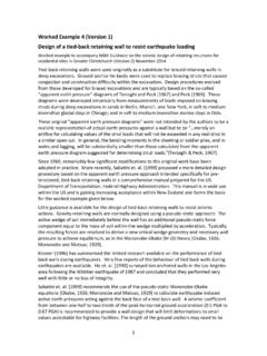
Worked Example 4 | Design of a tied-back retaining wall to ...
www.building.govt.nzDesign of a tied-back retaining wall to resist earthquake loading . Worked example to accompany MBIE Guidance on the seismic design of retaining structures for residential sites in Greater Christchurch (Version 2) November 2014 . Tied-back retaining walls were used originally as a substitute for braced retaining walls in deep excavations.

Earthquake geotechnical engineering practice
www.building.govt.nz2 Site and liquefaction considerations 2.1 Site characterisation One of the initial steps in the design of ground improvement is to develop a geotechnical model for the site which fits within the wider regional geology and geomorphology. This starts from review of …
Related documents
Acceptable Solutions and Verification Methods
www.building.govt.nz4.2 Sizing of downpipes 42 4.3 Installation of downpipes 42 5.0 Roof Gutters 42 5.1 Size of roof gutter 42 5.2 Materials44 5.3 Gradients44 5.4 Thermal movement 44 5.5 Overflow outlets 44 E1/AS1 Appendix A Rainfall intensities 45 Acceptable Solution E1/AS2 52 1.0 AS/NZS 3500.3 Stormwater Dec 2000 drainage52 Index 56 Contents Amend 4
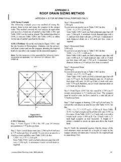
APPENDIX A ROOF DRAIN SIZING METHOD - ecodes.biz
www.ecodes.bizAPPENDIX A ROOF DRAIN SIZING METHOD (APPENDIX A IS FOR INFORMATIONAL PURPOSES ONLY) A101 Sizing Example The following example gives one method of sizing the primary drain system and sizing the scuppers in the parapet walls. This method converts the roof area to an equivalent roof area for a 4-inch rate of rainfall so that Table 1108.1 and
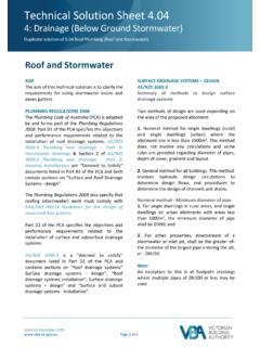
Drainage Below Ground Stormwater Sizing Drains and …
www.vba.vic.gov.aucalculations. (see Appendix A) SAA/SNZ HB114 for example calculations for typical roof styles. (see page 14 step 2) for the method using the slope factor for a pitched roof to an eaves gutter (hip & valley with no abutting vertical walls or flat roofs). The catchment area of a roof and any
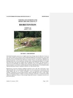
VIRGINIA DCR STORMWATER DESIGN SPECIFICATION No. …
swbmpvwrrc.wp.prod.es.cloud.vt.educollected in an underdrain and returned to the storm drain system. The underdrain consists of a perforated pipe in a gravel layer installed along the bottom of the filter bed. A bioretention facility with an underdrain system is commonly referred to as a Bioretention Filter. Bioretention can also be designed to infiltrate runoff into native soils.

Design Criteria for Sewers and Watermains
www.toronto.caAppendix C – Maps – contains a map showing which direction to open a watermain valve based on the district you are working in and a map showing the combined sewer areas. Appendix D – Utility Separations – contains minimum vertical and …
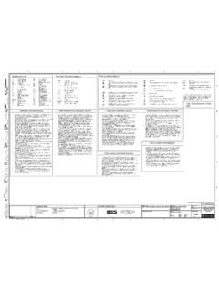
ABBREVIATIONS: FIRE PROTECTION SYMBOLS: FIRE ALARM …
gsiconstruct.com6. threadable thinwall, engineered pipe sizing, ie dynathread/dynaflow, and cpvc may not be used. 7. all materials used in the installation of this system(s) shall be new and of current issue. all materials shall be approved by ul and be in conformance with current edition of nfpa-13, as well as the authority having jurisdiction. 8.

Design Criteria for Sewers and Watermains
www.toronto.caiv January 2021 Design Criteria for Sewers and Watermains Expanded Transfer of Review Program ..... 29 Sewage Works Allowed Under the Transfer of Review