Transcription of Constructing Cavities - Building Performance
1 Constructing Cavities for wall claddingsTo be read in conjunction with Acceptable Solution E2/AS1 IntroductIon 1 2 .0 What does a cavIt y do? 2 th e 4ds 2 Wh en I s a cavIt y n eeded? 4 InstallIng Wall un derl ays 4 Flexible wall underlays 5 Rigid wall underlays 8 cavIt y bat tens 9 Timber cavity battens 9 Polystyrene cavity battens 9 Positioning battens 9 Support for vertical fixings 9 Support for horizontal fixings 11 Fixing battens 11 closIng off th e top of th e cavIt y 12 dr aInage an d ventIl atIon 13 cavIt y Walls over t Wo stor eys 17 InstallIng WIn doW an d door joIn ery 17 aIr seals 19 12.
2 0 Mor e I nforMatIon 20 This document has been prepared by the Department of Building and Housing (the Department) as guidance information in accordance with section 175 of the Building Act 2004. It is intended as guidance information only, and is not specific to any particular project. This document is not a substitute for professional advice. While the Department has taken care in preparing this document, it should not be relied upon as establishing compliance with all the relevant requirements of the Building Act or Building Code in all cases that may arise. This document is not a Compliance Document and may be updated from time to time. The latest version is available from the Department s website at booklet is based on the Acceptable Solution for Building Code Clause E2 External Moisture, E2/AS1 Third Edition, Erratum 1.
3 If further amendments are made to E2/AS1, information in this booklet may become out of generic claddings shown in some of the figures in this booklet are indicative only. For specific cladding requirements refer to E2 o n s t r u c tI n g c avI t I e s f o r Wa l l c l a d dI n g s I n t ro du c tI o n This booklet is a guide to drained and vented cavity construction for timber-framed buildings, as described in the Acceptable Solution for Building Code Clause E2 External Moisture (E2/AS1). It does not explain the cavity behind masonry veneer wall claddings. Drained and vented Cavities (referred to in this booklet as Cavities ) are an important component of weathertight construction in higher-risk situations.
4 Their proper construction is important to guard against the effects of are not intended as a drain down which water can be deliberately fed. Correctly installing the cladding is still the primary means of excluding water. Cavities act as a second line of defence to manage water that might inadvertently get past the timber-framed buildings in New Zealand, recent science and research has identified drainage and drying of water as critical functions of Cavities . This booklet will help you construct Cavities according to E2/AS1 to ensure buildings are well built and more information on materials, details and using common cladding materials, refer to E2/AS1. Copies of E2/AS1 are available to download free of charge from the Department of Building and Housing s website at c o n s t r u c tI n g c avI t I e s f o r Wa l l c l a d dI n g t h e 4 dsE2/AS1 is based on the 4Ds of weathertightness (a concept developed in Canada).
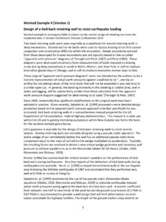
5 In this approach, Deflection , Drainage , Drying and Durability are the four key elements important to managing water on walls (see Figure 1). Deflection: The first line of defence is a well designed and constructed cladding system to deflect the water away. Drainage: A cavity provides a second line of defence by draining away water that may leak behind the cladding. Drying: By ventilating the cavity, any moisture that has not drained away is removed by drying . Durability: Materials for wall and cavity construction must be sufficiently durable to resist decay for a period that will allow time for a leak to be discovered and repaired. A masonry veneer cavity is different from the cavity described in this booklet.
6 With masonry veneer cladding, it is expected that some water may pass through the masonry veneer itself, so the cavity is wider and has top as well as bottom venting. (For information on masonry veneer refer to E2/AS1 Paragraph )2 .0 W h at do es a cavI t y do ?The cavity described in this booklet is intended as back-up protection if water leaks past the cavity constructed behind a cladding provides a method of managing water that might enter behind the cladding: through gaps or joins in the cladding around penetrations in the cladding, such as windows, doors or vents along the path of pipes, fixings or other elements that penetrate the cladding. The cavity separates the cladding material from the timber framing.
7 It protects the timber framing from any occasional leaking by providing a gap allowing water to drain down the back of the cladding and out through the base of the cavity. Any remaining moisture within the cavity is able to dry through ventilation provided along the bottom edge of the o n s t r u c tI n g c avI t I e s f o r Wa l l c l a d dI n g s 3figure 1: the 4ds of weathertightness4 Durability of materialsroof cladding2 Drainage ofwater down inside of claddingdirection of rain1 Deflection ofwater by eaves and claddingcavity3 Drying by ventilation (some diffusion of water through the structure also occurs)wall claddingwall framing4 c o n s t r u c tI n g c avI t I e s f o r Wa l l c l a d dI n g s4.
8 0 W h en I s a cavI t y n e ed ed ? (Refer to E2/AS1 Paragraph )E2/AS1 contains a risk matrix that requires the designer to give a score to each wall face of a Building . The score indicates the risk of water penetrating the cladding posed by the Building design. With this score, the designer refers to a selection of claddings in Table 3 of E2/AS1 (some without a cavity, some with a cavity) and chooses an appropriate cladding system. The designer includes the risk matrix score and calculations in Building consent documentation, and details the cladding in accordance with E2/AS1. You can download the guidance document External moisture A guide to using the risk matrix for free from the Department s website ( ) for more information on when a cavity is I n sta llI n g Wa ll u n d e r l ays The wall underlay is either a flexible wall underlay (paper-based or synthetic) or a rigid wall underlay (plywood or fibre cement) in accordance with E2/AS1 Table 23 ( Properties of roof underlays and Building wraps ).
9 Install the wall underlay directly over the framing. Install the cavity battens directly over the wall underlay as described in Cavity battens on page additional wall underlay is needed between the wall cladding and the cavity battens except in the following situations. Metal claddings need a separation layer between the cladding and cavity battens containing copper-based treatment (refer to Timber cavity battens, page 9). Stucco on a non-rigid backing needs a flexible wall underlay as the non- rigid wall underlay as follows to ensure water will be directed to the bottom of the cavity. Fitting the wall underlay correctly is essential, as the underlay helps form a second line of defence to protect the framing from moisture.
10 C o n s t r u c tI n g c avI t I e s f o r Wa l l c l a d dI n g s flexible wall underlays(Refer to Figure 2 and to E2/AS1 Paragraph )Run flexible underlays horizontally with the upper layer overlapping the lower by at least 75 mm. This will ensure the direction of laps sheds water to the vertical joins in the flexible underlay, lap at least 150 mm over a LOSP-treated timber can affect bitumen used in some paper-based wall underlays. Ensure the solvent in timber framing or cavity battens has evaporated before placing wall underlay and timber in 2: fitting flexible underlaymin 75 mm horizontal lapadditional flap of flexible wall underlay over upturn of head flashing or seal flashing to underlay with flexible flashing tapemin 150 vertical lap over stud6 c o n s t r u c tI n g c avI t I e s f o r Wa l l c l a d dI n g sAt windows, doors and other openings, cut the flexible underlay and dress into all sides of the opening (see Figure 3).