Transcription of acilities Development ManualF Wisconsin Department of ...
1 Page 1 Facilities Development Manual Wisconsin Department of TransportationChapter 11 Design Section 20 Cross Section Elements for Modernization of Urban Highways FDM 11-20-1 Modernization Dimensions and Design Classes August 17, General Modernization design criteria for various urban highway systems are given in this procedure. Attachment and Attachment contain modernization design criteria for urban highways. Modernization projects include what was formerly referred to as Reconstruction and New Construction projects and will still be sub-categorized by these project types in this section to clarify guidance.
2 The biggest difference between Reconstruction and New Construction-Type Modernization projects is that Reconstruction projects will be evaluated under the WisDOT Safety Certification Process (SCP) to determine the safety performance of the existing cross sectional and geometric features. This SCP information can be used to justify the use of lower end of the range design criteria and outside of the range design criteria when evaluated in conjunction with other appropriate Design Justification (DJ) information (environmental impacts, public input, significant costs) in the DSR.
3 Reconstruction projects will apply the S-2 Application as described in FDM New Construction projects cannot use the SCP because no existing cross sectional or geometric features or crash histories exist in which to analyze safety performance, however predictive safety benefit/cost analyses in conjunction with environmental process evaluations can be used to compare alternatives. New Construction projects will use the S-3 Application as described in FDM See FDM 11-15-1, FDM 11-1-20, FDM and FDM 11-38 for further information on the S-2/S-3 Applications, Design Study Report (DSR) Design Justifications (DJs), and the SCP for use on Modernization projects.
4 DJ approvals in the DSR are also available to use when needed to justify the preservation of existing features or the application of new cross sectional or geometric feature values outside of FDM design criteria values which are not initially recommended by the Safety Certification Process Document(SCD) or other safety analyses. See FDM 11-1-20 and FDM for information and guidance on the use of DSR Cross Slopes The pavements of urban roadways typically have crowns in the middle and slope downward towards both edges. The downward cross slopes should be in planes rather than curved (parabolic) sections.
5 Table shows the usual Lower and Upper cross slope rates to use: Table Cross Slope Rates for Urban Roadways Lanes Lower Upper Driving 2% 3% Parking, Turning, etc. 2% 4% Cross slope rates outside these ranges may be warranted in unique situations. Curbs or curb and Gutters The designs of curbs are based on whether the improved roadways will be defined as low speed urban, transitional, or, high speed urban. Designers must therefore first determine the types of roadways, t hen use the guidelines for those roadway types to determine the curb designs that may be needed. Roadways are defi ned as low speed, transitional, or, high speed based on two characteristics: - Cross-sections- Posted speeds (Regulatory speeds)Generally, urban roadways are ones that control surface drainage using curbs and may have enclosed storm sewer systems that may discharge into open channels.
6 As Table shows, roadways with urban cross sections and posted speeds of 40 mph or less are considered Low Speed Urban, whereas roadways with urban cross sections and posted speeds of 50 mph or greater are considered High Speed Urban. Other roadways are considered Transitional. Please note that the locations of roadways within the corporate limits of cities do not necessarily mean that the roadways have urban cross-sections. FDM 11-20 Cross Section Elements for Modernization of Urban Highways Page 2 Table Matrix for Determining Roadway Types Posted Speed 40 mph or less 45 mph 50 mph or greater Urban Cross Section Low Speed Urban Roadway Transitional Roadway High Speed Urban Roadway Normally, the methods of handling drainage determine the cross section.
7 Given the cross sections, designers then use the posted (regulatory) speeds or operating speeds to determine the types of roadways along with the information in the following paragraphs to select the appropriate curb designs. When designing curbs for Modernization roadways, the expected posted speeds are used. The posted speed limits are not required to correspond to the design speeds or to individual design elements within the projects . Consult with region traffic engineers to determine the appropriate posted speeds that will be implemented following completion of improvement projects.
8 (See Chapter 13 of the WisDOT Traffic Engineering Operation and Safety Manual1 (TEOpS 13) for guidance relating to posted speed limits). In cases of local roadways or connecting highways, als o consult with the local municipalities having jurisdiction over the roadways when determining the appropriate posted speed limits. When determining the acceptability of given curb designs (heights and offsets), consider other characteristics of the roadway corridors. In addition to drainage and the posted speeds, c onsider: - need to maximize capacity,- degree of adjacent roadside property Development ,- need for on-street parking- need for sidewalks- need for bicycle facility accommodations- frequency of access points- functional classification(s)- availability and cost of right-of-wayIncreases in any of these factors may make the character of the roadways more, low speed urban.
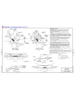
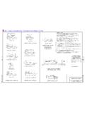
9 General curb Design Information Dimensions and details of recognized curb and gutter designs are on WisDOT s standard detail drawings web page ( ). Curbs can be categorized as either vertical face or sloping face. Table lists the standard WisDOT curbs shown in Chapter 16, and categorizes them as vertical face, 4-inch sloping face, or 6-inch sloping face. Gutter width is the distance between the gutter flange line and the curb face. Gutter widths are considered part of the offsets from the edges of the traveled ways to the faces of curbs. 1 WisDOT Traffic Engineering Operations and Safety Manual: FDM 11-20 Cross Section Elements for Modernization of Urban Highways Page 3 Table curb , curb & Gutter, and Inlet Covers per FDM Chapter 16 curb type Inlet Covers * Vertical Face Type A curb A, A-S, H, H-S, WM, S, V, Z Type A, 18-inch Z Type A, 30-inch A, A-S, H, H-S, WM, Z Type D curb A, A-S, H, H-S, WM, S, V, Z Type D, 18-inch Z Type D, 30-inch A, A-S, H, H-S, WM, Z Type K, 30-inch A, A-S, H, H-S, WM, Z Type L, 30-inch A, A-S, H, H-S, WM, Z Milwaukee: 18-inch Milwaukee: 22-inch Milwaukee.
10 31-inch R, W 4-inch Sloping Face Type A, 36-inch HM, HM-S Type D, 36-inch HM, HM-S Type G, 30-inch HM-GJ, HM-GJ-S Type J, 30-inch HM-GJ, HM-GJ-S Type T, 36-inch T Type R, 36-inch T 6-inch Sloping Face Type A, 36-inch F, HM, HM-S Type D, 36-inch F, HM, HM-S Type G curb HM-GJ, HM-GJ-S, S, V Type G, 30-inch HM-GJ, HM-GJ-S Type J curb HM-GJ, HM-GJ-S, S, V Type J, 30-inch HM-GJ, HM-GJ-S *Inlet covers can fit curb heights and curb and gutter widths. Some adjustments may be required. Also, checkhydraulic capacities and the safety for bicycles, pedestrians, and disabled approach is to widen the gutters at the inlet locations.
