Transcription of Adafruit MAX31865 RTD PT100 or PT1000 Amplifier
1 Adafruit MAX31865 RTD PT100 or PT1000 AmplifierCreated by lady ada updated on 2021-11-15 06:49:40 PM EST Adafruit IndustriesPage 1 of 3036667899101313141516161617171818192021 212222232424252526272828292930 Table of ContentsOverviewPinouts Power Pins: SPI Logic pins: Sensor Terminal Blocks Configuration JumpersAssembly Prepare the header strip: Solder!RTD Wiring & Config 4-Wire RTDs 3-Wire RTDs 2-Wire RTDs How To Wire Up! 4-Wire Sensors 3-Wire Sensors 2 Wire SensorArduino Code SPI Wiring Download Adafruit_MAX31865 library Attach PT100 or PT1000 RTD Load Demo More Accuracy Library Reference Reading Resistance Calculating TemperaturePython & CircuitPython CircuitPython Microcontroller Wiring Python Computer Wiring CircuitPython Installation of MAX31865 Library Python Installation of MAX31865 Library CircuitPython & Python Usage Full Example CodePython Files Schematic & Fabrication Print Adafruit
2 IndustriesPage 2 of 30 Overview For precision temperature sensing, nothing beats a Platinum RTD. Resistancetemperature detectors (RTDs) are temperature sensors that contain a resistor thatchanges resistance value as its temperature changes, basically a kind of thermistor. Inthis sensor, the resistor is actually a small strip of Platinum with a resistance of 100 or1000 ohms at 0 C, thus the name PT100 / PT1000 . Compared to most NTC/PTCthermistors, the PT type of RTD is much more stable and precise (but also moreexpensive) PT's have been used for many years to measure temperature in laboratoryand industrial processes, and have developed a reputation for accuracy (better thanthermocouples), repeatability, and stability.
3 Adafruit IndustriesPage 3 of 30 However, to get that precision and accuracy out of your PT100x RTD you must use anamplifier that is designed to read the low resistance. Better yet, have an Amplifier thatcan automatically adjust and compensate for the resistance of the connecting wires. Ifyou're looking for a great RTD sensor, today is your lucky day because we have alovely Adafruit RTD Sensor Amplifier with the MAX31865 've carried various MAXIM thermocouple amplifiers and they're great - butthermocouples don't have the best accuracy or precision, for when the readings mustbe as good as can be.
4 The MAX31865 handles all of your RTD needs, and can evencompensate 3 or 4 wire RTDs for better accuracy. Connect to it with any Adafruit IndustriesPage 4 of 30microcontroller over SPI and read out the resistance ratio from the internal ADC. Weput a resistor as a reference resistor on the breakout. We have some examplecode that will calcuate the temperature based on the resistance for PT100 version of the breakout uses 430 The PT1000 version uses 4300 We even made the breakout 5V compliant, with a regulator and level shifting, soyou can use it with any Arduino or microcontrollerEach order comes with one assembled RTD Amplifier breakout board.
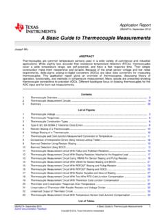
5 Also comeswith two 2-pin terminal blocks (for connecting to the RTD sensor) and pin header (toplug into any breadboard or perfboard). A required PT100 or PT1000 RTD is notincluded! (But we stock them in the shop). Some soldering is required to solder theheaders and terminal blocks to the breakout, but it's an easy task with soldering tools. Adafruit IndustriesPage 5 of 30 Pinouts The MAX31865 is a tiny surface mount chip, and it needs a lot of other parts to makeit work, so we've got it on a nice breakout board for you.
6 You can control the chip andread data from it using the breakouts at the bottom. Let's go thru these!Power Pins:Vin - this is the power pin. Since the chip uses 3 VDC, we have included avoltage regulator on board that will take 3-5 VDC and safely convert it down. Topower the board, give it the same power as the logic level of yourmicrocontroller - for a 5V micro like Arduino, use 5V3Vo - this is the output from the voltage regulator, you can grab up to100mA from this if you likeGND - common ground for power and logicSPI Logic pins:All pins going into the breakout have level shifting circuitry to make them 3-5V logiclevel safe.
7 Use whatever logic level is on Vin!SCK - This is the SPI Cloc k pin, its an input to the chipSDO - this is the Serial Data Out / Microcontroller In Sensor Out pin, for datasent from the MAX31865 to your processor Adafruit IndustriesPage 6 of 30 SDI - this is the Serial Data In / Microcontroller Out Sensor In pin, for data sentfrom your processor to the MAX31865CS - this is the Chip Select pin, drop it low to start an SPI transaction. Its an inputto the chipIf you want to connect multiple MAX31865 's to one microcontroller, have them sharethe SDI, SDO and SCK pins.
8 Then assign each one a unique CS (Ready) - is a data-ready indicator pin, you can use this pin to speed upyour reads if you are writing your own driver. Our Arduino driver doesn't use it tosave a pinSensor Terminal BlocksIf you have an RTD sensor, you need to connect it somehow! the terminal block areais where you can clamp down to the sensor are four contacts, but you can use 2, 3 or 4 wire sensors. You may need tosolder or jumper some pads depending on how many wires you want to use. You canalso use a 3 or 4 wire sensor as a 3-wire or 2-wire sensor (just don't connect the extrawires).
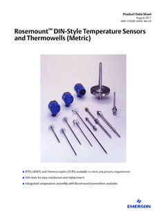
9 Check the RTD wiring page for details on how to connect the sensor you've got! Adafruit IndustriesPage 7 of 30 Configuration JumpersBy default the sensor is wired up for 4-wire RTD usage but can be set up for 2 or 3wire very 4-wire usage, do nothing with the jumpers!For 3-wire usage. Solder closed the jumper labeled 2/3 Wire and cut the wireconnecting the left side of the 2-way jumper right above Rref. Then solder closed theright side labeled 3 For 2-wire usage, solder closed the two triangular jumpers below the terminal blocks(or put short wire jumpers between the two terminal blocks on either side (essentiallyjumpering the two right side terminal holes together, and same for left side)Check the RTD wiring page for details on how to connect the sensor you've got!)
10 Adafruit IndustriesPage 8 of 30 Assembly Prepare the header strip: Cut the strip to length if necessary. It willbe easier to solder if you insert it into abreadboard - long pins down Adafruit IndustriesPage 9 of 30 Solder! Be sure to solder all pins for reliableelectrical contact.(For tips on soldering, be sure to checkout our Guide to ExcellentSoldering ( )). Adafruit IndustriesPage 10 of 30 Next we will solder in the two blocks used to connect power &the motor to the breakout board. Make sure the open parts of theterminals face outwards so you can easilyconnect wires To make it easier to keep these in place,you can use some tape to hold down thetwo header pieces.