Transcription of Adding shutdown feature to MC33063A, …
1 Application Report SLLA339 February 2013 1 Adding shutdown feature to mc33063a , mc34063a switching regulators Ronald Michallick Standard Linear and Logic ABSTRACT The mc33063a and mc34063a switching regulators are inexpensive and easy to use. However, the devices do not have a shutdown pin to disable the output power. This application report demonstrates methods to incorporate an output shutdown feature using external components to disable the power switch. Figure 1 SLLA339 2 Adding shutdown feature to mc33063a , mc34063a switching regulators shutdown implementation In this application note, all references to the mc34063a also apply to the extended temperature range mc33063a . These regulators are economical and easy to use, but do not have a shutdown feature to turn the output off. This application note demonstrates three methods to implement a shutdown feature with the mc34063a .
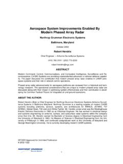
2 The mc34063a (figure 1) supplies fixed on time drive to the internal power switch when the Comparator inverting input (abbreviated as Cii ) is less than the internal reference voltage. When the Cii is greater than the internal reference, the output switch will remain off. Therefore, keeping the Cii pin above will stop the output switch (the oscillator will continue to run) and the output will decay to zero volts when used as a buck or inverting regulator. However, the boost setup will have an output voltage that will be one diode drop less than input voltage. Even with the switch disabled the catch diode conducts from VIN to VOUT. The recommended range for the Cii input is to 40V relative to the ground pin. A diode, PMOS transistor or PNP transistor can be used to pull the Cii pin to any level greater than (relative to GND pin) to stop the mc34063a switch, but the added circuitry must not affect the feedback network when the mc34063a is enabled.
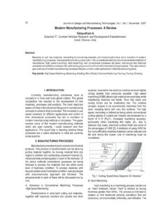
3 For boost operation, a load switch should be added in series with the input power source. A load switch can also be used for the buck and inverting operation. Table 1 shows which shutdown method can be used with various MC33063 topologies. Table 1. shutdown method and topology compatibility Table shutdown Method Buck Inverting Boost Load Switch to VCC Yes Yes Yes PNP/PMOS to Cii Yes Yes No Diode to Cii Yes No No SLLA339 Adding shutdown feature to mc33063a , mc34063a switching regulators 3 Buck regulator shutdown circuit example (using diode to Cii) Only one component (D1) is needed to disable the mc34063a and shut down the 5V output when controlled by logic. When the logic input is low, D1 is reversed biased and has no effect on the output voltage (VOL + VF < ). When the logic input is high, D1 is forward biased and will pull Cii, pin 5, up to (VOH VF).
4 VF is the D1 diode s forward voltage. With the power switch forced off, VOUT will drop to near zero and the input current will be the mc34063a bias current typically R2 will pass a small current, (VOH-VF)/R2, to the output node. The current required from the logic input is ()()OHF121111V-V x x 286 += + = If the logic input source was powered by then the VOH voltage on the cathode of D1 would not be high enough to reliably pull Cii above For logic, the PNP example in the inverting regulator shutdown circuit example should be used instead. SLLA339 4 Adding shutdown feature to mc33063a , mc34063a switching regulators Inverting regulator shutdown circuit example (using PNP to Cii) For the inverting regulator, two components (R3&Q1) are needed to disable the mc34063a and shut down the -12V output.
5 When the logic input is high, Q1 is cut off and no collector current will flow. Therefore, Q1 has no effect on the output voltage. When the logic input is low, current will flow through the Q1 base emitter junction. With sufficient base current, Q1 will pull pin 5 (Cii) voltage close to the logic supply voltage. With the power switch forced off, VOUT will drop to near zero and the input current will be the mc34063a bias current typically However, the mc34063a bias current (pin 4) and R1 current will flow through the Schottky diode and inductor to ground if the output load is light. In this case a small positive voltage, about + will be present on the output capacitor (and the load) during shutdown . Contact the capacitor s manufacturer to verify that this will be safely tolerated. The current required from the low logic input is AkVVVR - V - V3 OLBEL= = Q1 s collector current will be about 1211 x VLRR += x += The PNP transistor can be replaced with a PMOS transistor if preferred.
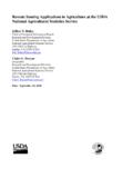
6 The PMOS threshold voltage should be chosen to keep the transistor off with VOH input and pass required current with VOL input. R3 can remain to limit peak capacitive gate current. SLLA339 Adding shutdown feature to mc33063a , mc34063a switching regulators 5 The output enabled Cii voltage (relative to system ground) is VOUT + = ; therefore the single diode circuit used in the buck application example can not be used because the diode would be always forward biased. Boost regulator shutdown circuit example (using load switch) Using a load switch as a shutdown control is common solution that works for any regulator. It is included here because raising Cii voltage is only partially effective for shutdown of a boost topology switch regulator circuit. The standard boost regulator circuit has an external path from mc34063a VCC pin to VOUT; therefore a load switch is required to break the path from input voltage to output voltage.
7 The TPS27081A load switch is used to turn the supply voltage to the mc34063a on and off with a controlled slew rate that limits the peak current into the 100 F capacitor during turn on. A load switch can also be used for the buck and inverting applications. This method provides a true shut down implementation. In addition to turning off the output, the total off current with 0V on the TPS27081A ON/OFF pin is less than 1 A. SLLA339 6 Adding shutdown feature to mc33063a , mc34063a switching regulators Conclusion Disabling the internal power switch by external raising the comparator inverting input voltage effectively shuts down the output voltage for buck and inverting (buck/boost) topologies. It also reduces reduced the output voltage in a boost topology to one diode drop below VIN. Only one or two additional components are needed to interface to logic outputs in a wide range of logic levels.
8 The mc34063a bias current and feed back resistors still consume a few milli-amperes of current because the most of the mc34063a internal circuitry is still active. If this shutdown current draw is unacceptable then a load switch or different regulator with integrated shutdown should be used. IMPORTANTNOTICET exasInstrumentsIncorporatedanditssubsidi aries(TI)reservetherighttomakecorrection s,enhancements,improvementsandotherchang estoitssemiconductorproductsandservicesp erJESD46,latestissue,andtodiscontinueany productorserviceperJESD48, (alsoreferredtohereinas components ) aresoldsubjecttoTI s ,in accordancewiththewarrantyin TI s ,testingofallparametersofeachcomponentis productsandapplications, ,eitherexpressorimplied,is grantedunderanypatentright,copyright,mas kworkright,orotherintellectualpropertyri ghtrelatingtoanycombination,machine,orpr ocessin licensetousesuchproductsorservicesora licensefroma thirdpartyunderthepatentsorotherintellec tualpropertyofthethirdparty,ora TIdatabooksordatasheetsis permissibleonlyif reproductionis withoutalterationandis accompaniedbyallassociatedwarranties,con ditions,limitations, is solelyresponsibleforcompliancewithallleg al,regulatoryandsafety-relatedrequiremen tsconcerningitsproducts,andanyuseofTIcom ponentsin itsapplications, hasallthenecessaryexpertisetocreateandim plementsafeguardswhichanticipatedangerou sconsequencesoffailures,monitorfailuresa ndtheirconsequences.
9 TI s goalis , FDAC lassIII(orsimilarlife-criticalmedicalequ ipment)unlessauthorizedofficersofthepart ieshaveexecuteda enhancedplastic solelyattheBuyer's risk,andthatBuyeris solelyresponsibleforcompliancewithallleg alandregulatoryrequirementsin , , , :TexasInstruments,PostOfficeBox655303,Da llas,Texas75265 Copyright 2013,TexasInstrumentsIncorporat