Transcription of ADIABATIC PLASTIC DEFORMATION - THE CASE …
1 Corresponding author: Alexandru Epureanu Domneasca Street 47, Galati 800008 Romania, email: ADIABATIC PLASTIC DEFORMATION - THE case OF CUTTING PROCESS C. Maier, V. Vacarus , M. Banu, A. Epureanu Department of Manufacturing Science and Engineering, Dunarea de Jos University of Galati Romania ABSTRACT: Numerical and experimental research program was developed taking into account the high speed machining particularities. The results was analyzed by approaching the cutting process as ADIABATIC PLASTIC DEFORMATION process. Firstly, the process of material detaching was identified as thermodynamic transformation, and the tool rake surface and virtual finished surface was considered as the limit of the thermodynamic system in which this transformation took place. The ADIABATIC cutting process was defined as the cutting process in which: i) hole the mechanical work of the cutting force can be find as internal energy variation of the detached material, ii) hole the detached material can be find in the chips resulted and iii) the superficial layer doesn t support any irreversible transformations during the cutting process.
2 For the process ADIABATIC character evaluation a specific metrics was proposed. The numerical studies was based on cutting simulation using Marc commercial software. For experimental studies, an experimental setup was build being able to develop the interrupting process with cutting speed up to 36 m/s. Thermal field study was performed using thermo vision camera with 50 frames/s frequency. The experimental tests confirmed the experimental result. KEYWORDS: cutting thermodynamic system, ADIABATIC cutting process, surface layer, high speed machining. 1. INTRODUCTION Salomon [1] was the first scientist to state that if the cutting speed is significantly increased, than the tool thermal loading should decrease and consequently will diminish its negative effects. Different opinions considering Salomon statement emerged concerning significant differences between chip temperature and cutting tool temperature, on one hand, and on the other hand, between these two and the part temperature.
3 According to Shaw [2], 90% of the heat is contained in the chip, 5% in the part and 5% in the cutting tool. Others [3,4], suggested that 80% of the heat is transferred in the chip and 10% to each cutting tool and part processed. All agree that in case of high-speed the heat is maintained in the chip, what means that the heat in the tool-chip interface to increase, while the part is maintained relatively cold [4,5]. Also, the statement that if the cutting speed are high, than the tool wear is diminished , as a consequence of decrease of the specific heat amount transferred in the tool, could be confirmed only in the interrupted cutting. High material removal rate, the short time of the heat to be diffused in the part, the fact that the chip is transporting the heat from cutting, all lead to the idea of a plausible scenario.
4 In the paper it is studied high speed interrupted cutting. The aim is to evaluate the possibility that the thermal influence on the superficial layer of the processed surface to be diminished, in order not to modify microstructure and mechanical properties of the layer. To aim this, the cutting process was approached as ADIABATIC process, developed in a specific thermodynamic system. By means of numerical simulation, it was studied the ADIABATIC character of the cutting process. The results obtained were validated by experimental test. In this paper, in section 2, it is presented physical modeling of the cutting process as ADIABATIC PLASTIC DEFORMATION process. In section 3, it is presented the obtained results both by numerical and experimental tests.
5 Finally, in section 4 are summarized the main conclusions resulted 2. ADIABATIC PLASTIC DEFORMATION DURING THE CUTTING PROCESS Thermodynamic cutting system will be modeled as an open thermodynamic system. Such thermodynamic system is composed of matter flow, which is performing several energetic transformation during its pass through system. It is considered matter flow m which is flowing in the thermodynamic system, with specific internal energy u1. Proceedings of the 8th WSEAS International Conference on SYSTEM SCIENCE and SIMULATION in ENGINEERINGISSN: 1790-276963 ISBN: 978-960-474-131-1As output of the system there is the same matter flow m with modified internal energy u2. Matter flow m is given by equation (1) bellow: mvs= t (1) where: = material density; v = cutting speed; s =feedrate; t =depth of cut.
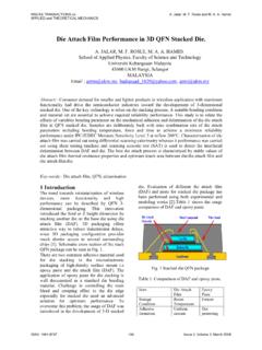
6 Also other outputs are thermal flows qm, qp, qs, representing the heat amount in the time unit exchanged by material with respectively the environment, the tool and the part, as represented in The material subjected to the energetic transformation in the cutting thermodynamic system is the detached layer. In a spatial representation, the thermodynamic system is surrounded by the following limits ( ): separation limit between the thermodynamic system and the part P is the surface AD; separation limit between the tool S and the thermodynamic system is the AB contact surface between the tool and the chip; separation limit between the thermodynamic system and the environment is the C1C2 surface of the part.
7 Figure 1: Modeling as open system Input surface of the matter flow is the undeformed chip section DC2 and the output surface of the matter flow is the section BC1 of deformed chip A. During the thermodynamic cycle developed by the matter flow, the workflow exchange with the exterior is emerging, represented by power p given by equation (2) bellow: zpFv= (2) where: Fz = is the main cutting force; v = cutting speed. The heat exchange Q is given by equation (3) bellow: mpQq q q=++a (3) where qm,qp, and qa are the heat exchanged with environment, part and tool respectively. The internal energy variation U is given by equation (4) bellow: 21Um(u u) = (4) The thermodynamic cycle subjecting the material is described by the first thermodynamic principle as in (5): 12muqmup+=+ (5) b) Modeling as closed system Let s consider a limited time of the thermodynamic system working.
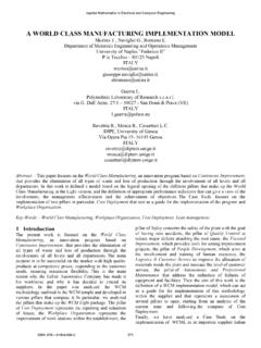
8 An example will be the particular case of interrupted cutting. Thermodynamic system can be conceived as a closed thermodynamic system ( ). Figure 2: Modeling as closed system In this case it can be considered, as separation limit of the thermodynamic system, the final part surface resulted and the contact surface between the tool and the chip. The material which is subjected to energetic transformation is the detached chip with mass M, given by equation (6): Mstl= (6) where: l = cutting length, represented by the AB arc. Mechanical work, L, is that of the cutting force Fz accomplished on length l of the tool trajectory, given by equation (7): zLFl= (7) The heat exchange Q is given by equation (8): psQQ Q=+ (8) where Qp and Qs are representing the heat dispersed by the part, and respectively by the tool, during chip detachment.
9 Internal energy variation , corresponding to the thermodynamic cycle is given by equation (9): U UMcT = (9) where: c = specific heat of the workpiece material; T = material temperature increase when the chip is formed. The first thermodynamic principle it is represented by: UQL = Proceedings of the 8th WSEAS International Conference on SYSTEM SCIENCE and SIMULATION in ENGINEERINGISSN: 1790-276964 ISBN: DEFINITION OF THE CUTTING ADIABATIC PROCESS In thermodynamics, the transformation where Q=0 it is called ADIABATIC and it is studied along other typical transformation, such as isotherm, isocore and isobar transformation. In the particular case of thermodynamic system associated with the cutting process, we will consider that the transformation is ADIABATIC if the heat exchange with the surface layer is null.
10 We conclude, that the superficial layer, during the ADIABATIC cutting process is subjected to null thermal influence. Perfect ADIABATIC transformation does not exist in nature. This is the reason for the ADIABATIC transformation is just a reference, any real transformation has relative ADIABATIC character. Moreover we will consider the ADIABATIC cutting as a reference with the significance that the thermo-mechanic aggression on the superficial layer is null, the separation limit between surface and cutting edge is narrow and the mechanical wok of the cutting force is find in the internal energy variation. To evaluate the ADIABATIC character of the cutting we propose a metrics based on the such called ADIABATIC index , IA, defined by equation (10): sasaa0 TTTIA 1 TTT = = (10) where: - Ta = chip temperature; Ts = superficial layer temperature; T0=detached material temperature before cutting.