Transcription of Air Release Valve - Val-Matic Valve & …
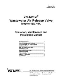
1 Manual No. ARCL-OM1-1 Air Release Valve Series 38, 45, 50 (Compound Lever Type) Operation, Maintenance and Installation Manual INTRODUCTION .. 1 RECEIVING AND 1 DESCRIPTION OF OPERATION .. 1 2 Valve CONSTRUCTION .. 2 MAINTENANCE .. 3 TROUBLESHOOTING .. 3 DISASSEMBLY .. 3 4 PARTS & SERVICE .. 4 WARRANTY .. 5 Valve AND MANUFACTURING CORP. 905 Riverside Dr. Elmhurst, IL 60126 Phone (630) 941-7600 Fax (630) 941-8042 1 Val-Matic 'S AIR Release Valve (Compound Lever Type) OPERATION, MAINTENANCE AND INSTALLATION INTRODUCTION This manual will provide you with the information to properly install and maintain the Valve to ensure a long service life.
2 The Air Release Valve has been designed with stainless steel trim to give years of trouble-free operation. The Air Release Valve is typically mounted at the high points in a piping system to automatically remove pockets of air as they accumulate. The Valve can also be used to slowly Release air in tanks and pump casings. Note: This Valve is not intended for fluids containing suspended solids such as wastewater. For wastewater and other high turbidity applications, use Val-Matic Series 48A & 49A Sewage Air Release valves . The Valve is a float-operated, resilient-seated Valve designed to handle clean fluids.
3 The Maximum Working Pressure and Model No. are stamped on the nameplate for reference. RECEIVING AND STORAGE Inspect valves upon receipt for damage in shipment. Handle all valves carefully without dropping. valves should remain boxed, clean and dry until installed to prevent weather related damage. For long term storage greater than six months, the Valve must remain in the box and stored indoors. Do not expose Valve to sunlight or ozone for any extended period. DESCRIPTION OF OPERATION The Air Release Valve is designed to automatically remove air pockets at the high points in a piping system. The Valve , as shipped, is a normally open Valve and will slowly vent air through the top orifice.
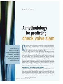
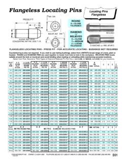
4 As fluid enters the Valve , the float will rise, closing the orifice. As air accumulates in the piping system and enters the Valve , the float drops allowing the venting orifice to open. FIGURE 1. Compound Lever AIR Release Valve The lever mechanism provides mechanical advantage for the float. During system operation, the pipeline pressure exerts a strong upward force on the sealing component, the orifice button. The lever mechanism magnifies the weight of the float so that the orifice will open under high pipeline pressures. Additional ports are provided for flushing, testing and draining purposes.
5 CAUTION: This Valve is not intended for fuel service or fluids containing suspended solids. 2 CAUTION: INSTALLATION The installation of the Valve is important for its proper operation. valves must be installed at the system high points in the vertical position with the inlet down. For pipeline service, a vault with freeze protection, adequate screened venting, and drainage should be provided. During closure, some fluid discharge will occur so vent lines should extend to an open drain area in plant service. A shut-off Valve should be installed below the Valve in the event servicing is required. Valve CONSTRUCTION The standard Air Release Valve body and cover are cast iron.
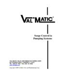
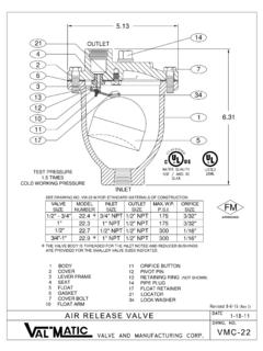
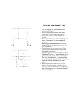
6 See the specific Materials List submitted for the order if other than standard cast iron construction. All internal components are stainless steel with the exception of the orifice button which is resilient. The general details of construction are illustrated in Figure 2. The body (1) is threaded for connection to the pipeline. The seat (4) is threaded into the cast cover (2). TABLE 1. AIR Release Valve PARTS LIST x ITEM DESCRIPTION MATERIAL 1 Body Cast Iron 2 Cover Cast Iron 3 Lever Frame* Stainless Steel 4 Seat* Stainless Steel 5 Float* Stainless Steel 6 Gasket* Non-Asbestos 7 Cover Bolt Alloy Steel 8 Retaining Screw* Stainless Steel 10 Float Arm* Stainless Steel 11 Orifice
7 Button* Buna-N 12 Pivot Pin* Stainless Steel 13 Retaining Ring* Stainless Steel 14 Pipe Plug Iron 17 Float Retainer* Stainless Steel 18 Lock Nut* Stainless Steel 19 Link* Stainless Steel 21 Locating Pin Stainless Steel 22 Orifice Button Arm* Stainless Steel 30 Washer* Stainless Steel 33 Clevis* Stainless Steel 34 Lock Washer* Stainless Steel *RECOMMENDED REPAIR PART KIT Install Valve with "INLET" port down or leakage will occur.
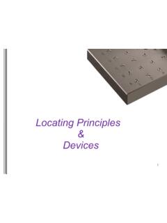
8 FIGURE 2. Compound Lever AIR Release Valve 3 MAINTENANCE The Air Release Valve requires no scheduled lubrication or maintenance. INSPECTION: Periodic inspection to verify operation can be performed. A manual drain Valve can be installed in the lower drain plug to perform this operation as shown in Figure 3. Figure 3. Inspection Piping 1. With the inlet shutoff Valve open, partially open the drain Valve until flow can be heard. If the air Valve is working properly, water should be exhausted from the drain Valve . If air is exhausted, follow steps 2-6. 2. Close the inlet shutoff Valve . 3. Slowly open the drain Valve to allow the fluid in the Valve to drain.
9 4. Close the drain Valve . 5. Slowly open the inlet shutoff Valve to fill the Valve with water. Observe the seating action and verify that the Valve closes without leakage. 6. If leakage occurs, the Valve should be removed and inspected for wear or possible damage from foreign matter. TROUBLESHOOTING Several problems and solutions are presented below to assist you in troubleshooting the Valve assembly in an efficient manner. Leakage at Bottom Connection: Tighten Valve threaded connection. If leak persists, remove Valve and seal threads with thread sealant. Leakage at Cover: Tighten bolts per Table 2, replace gasket.
10 Valve Leaks when Closed: Flush Valve to remove debris. Disassemble and inspect seat, orifice button, and float. NOTE: Many floats contain sand for weight but if water is detected, replace float. Valve not Venting Air: Check that operating pressure does not exceed Working Pressure on nameplate. Perform inspection steps 2-6 and disassemble Valve if problem persists. DISASSEMBLY The Valve can be disassembled without removing it from the pipeline. Or for convenience, the Valve can be removed from the line. All work on the Valve should be performed by a skilled mechanic with proper tools. No special tools are required.