Transcription of Altivar 212 Drive - Schneider Electric
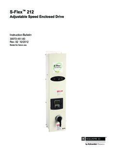
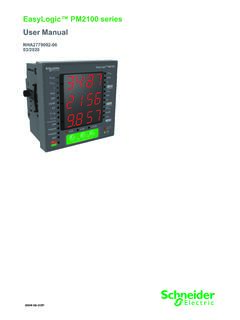
1 Altivar 212 DriveSelection GuideMake the most of your energySMVariable speed drives for asynchronous motors used in centrifugal pump and fan applications2 Altivar 212 Drive SelectionAltivar 212 Drive Selection The Altivar 212 Drive is intended for use with three-phase asynchronous motors for variable torque pump and fan applications. Select the Altivar 212 Drive using the nameplate voltage and full load ampere rating of the motor nameplate and the table below. The Altivar 212 Drive includes 3 logic inputs, 2 analog inputs, 1 analog output and 2 relay outputs (with 1 NO and 1 NO/NC contacts). It includes integrated 4 digit, 7 segment LED dispay with 7 button keypad, as well as RJ45 Modbus port, plus a 4 screw removable terminal block for software selectable BACnet, Modbus, METASYS N2 or APOGEE P1 communication protocols.
2 LonWorks is available in an option card. These horsepower, kW and continuous ampere ratings apply to default switching frequency and maximum 40 C ambient. Refer to the installation manual for derating curves as a function of switching frequency, ambient temperature and mounting conditions. IP20 Altivar 212 drives can be installed as UL Type 1 with the optional conduit box when following instruction in the Installation Manual. To select an Altivar drives with Class B EMC filter, add the letter C to the end of the standard catalog number. C Late 3Q 2011 Input line voltageEnclosure ratingThree-phase motor powerContinuous Output currentIP 20 Open style productType 1 conduit kit (purchase ATV212 and conduit Kit for Type 1 installation)Type 12/IP54 HPkWACatalog numberQTYF rame sizeCatalog numberQTYC atalog number CQTYF rame size208 1VW3A31814 1VW3A31814 1VW3A31814 2VW3A31815 2VW3A31815 3VW3A31816 3VW3A31816 4VW3A31817 201561 ATV212HD15M3X 4VW3A31817 4VW3A31817 302288 ATV212HD22M3X 5VW3A9206 4030117 ATV212HD30M3X 7VW3A9208 380/480 C4VW3A31817 212 Accessories and OptionsUser interface optionsFor use withCatalog numberQTYR emote LCD display keypadAltivar 212, 312, 32 , 61, 71VW3A11018 line, 24 characters per line, plain text, 8 keys, rotary wheel, 60 C IP54 rated Remote LCD keypad mounting accessories IP54 rated kit for remote mounting LCD keypad on enclosure doorVW3A1101VW3A1102 Clear plastic door for use with VW3A1102 for IP65 rating and tamper resistanceVW3A1102VW3A1103 Female/Female right angle RJ45 adaptor.
3 To connect cable and keypad.*(*not required if using VW3A1102) VW3A1101VW3A1105 Remote LCD keypad mounting cables equipped with two RJ45 connectors 1 meter lengthVW3A1101VW3A1104R103 meter lengthVW3A1101VW3A1104R305 meter lengthVW3A1101VW3A1104R5010 meter lengthVW3A1101VW3A1104R100 Multi-loaderAltivar 12, 212, 312, 32 Altistart 22VW3A8121 Use to copy configurations between like drives, PC Soft or SoMove PC software SoftwareFor use withCatalog numberPCSoft Altivar 21 and 212 Download at software use for: configuring, monitoring and trouble shooting Alitvar 212 drivesRequires one of two cables (noted below) to connect a PC to the RJ45 Modbus port on the Drive USB/RS485 cable: equipped with USB connector and RJ45 connectorAltivar and AltistartTCSMCNAM3M002 PRS 232-RS485 converter with SUB-D and RJ45 port, cable with two RJ45 connectorsAltivar 212VW3A8106 SoMove MobileAltivar 212 Download at for compatible mobile phones provides wireless interface similar to the LCD displayRequires Modbus to Bluetooth adaptor to connect phone and Altivar 212 Drive Modbus Bluetooth adaptor.
4 Connects to RJ45 Modbus port on the driveAltivar 12, 212, 312,61, 71VW3A8114 Communication optionFor use withCatalog numberLonWorks communication option cardAltivar 212VW3A21212 Provides 4 screw terminal block for connection to LonWorks networkInstall in place of standard control board that comes mounted in the Altivar 212 driveThe I/O count is reduce to 3LI, 1 AI and 1 NO/NC relay Mounting kitFor use withCatalog numberDIN rail mounting kitAltivar and Altivar For installation on to 35mm wide DIN rail VW3A1101VW31101, VW31102, VW31103, VW3A1104R10VW3A8121 PCSoft SoftwareSoMove Mobile SoftwareVW3A212124 Altivar 212 Drive Technical CharacteristicsEnvironmental SpecificationsTemperature ratings0 to + 40 C operational without de-rating, up to 60 C with de-rating (see installation manual for deratings)Altitude ratingsUp to 3,300 ft (1,000 meters) without de-rating, de-rate nominal current by 1% for each additional 330 ft ( 100m) up to 10,000 ft ( 3,000 m)Limit to 6,600 ft (2,000 m) if supplied by corner grounded distribution systemHumidityUp to 95% non-condensing , IEC 60068-2-3 Vibration mm peak to peak from 3 to 13 Hz conforming to EN/IEC 600068-2-6, 1 gn from 13 to 200 Hz conforming to IEC/EN 60068-2-8 Shock resistance15 gn for 11 ms conforming to IEC/EN 60068-2-27 Pollution degree1 HP to 25 HP @ 200/240 V, 1 HP to 5 HP @ 380/480 V: Pollution degree 2 per IEC/EN 61800-5-1, 30 HP to 40 HP @ 200/240 V, 30 HP to 100 HP @ 380/480 V: Pollution degree 3 per IEC/EN 61800-5-1 Degree of protection.
5 ATV212 H range ATV212 W rangeIP20, Conformal coating per IEC 60721-3-3 classes 3C2 and 3S2, Type 1 with optional conduit kit IP54/Type 12, Conformal coating per IEC 60721-3-3 classes 3C2 and 3S2 Electrical SpecificationsInput voltage and HP range ATV212 W is available in 380/480 range only200 15% to 240 +10%, Three phase input, Three phase output, 1 HP to 40 HP380 15% to 480 +10%, Three phase input, Three phase output, 1 HP to 100 HPInput frequency50 Hz -5% to 60 Hz +5%Galvanic isolationGalvanic isolation between power and control (inputs, outputs and power supplies) Drive input power sectionSix pulse bridge rectifier Drive output power sectionIGBT inverter with pulse width modulated outputPower factorAbove 99%EfficiencyAbove 98% at full loadSwitching frequencySelectable from 6 to 16 kHz, 12 kHz nominal rating for 1 HP to 20 HP @ 200/240 V, 380/480 VSelectable: 6 to 16 kHz, 8kHz nominal rating for 30 HP to 40 HP @ 200/240 V, 30 HP to 100 HP @ 380/480 VAcceleration and deceleration to 3200 seconds in seconds incrementsFrequency output to 200 hertzSkip frequenciesThree adjustable skip frequency bandsSpeed range1 to 10 Integrated motor protectionClass 10 electronic overload protectionAsynchronous motor control profilesSensorless flux vector, 2 point volts/hertz, quadratic volts/hertz, energy savings mode.
6 A optimization motor algorithm that automatically optimizes voltage based on loadTransient over current110% nominal for 60 seconds, 180% for 2 secondsEmbedded functionsOver 50 functions dedicated to pump and fan applicationsUser interfaceOn board: 5 LED indicators for various functions, 4 digit, 7 segment LED display with 7 button keypad for: Run, Stop/Reset, Local/remote, speed up, speed down, Mode selection and Enter. Quick start menu, fault history, I/O mapping, last-used menus, status monitoring and self diagnostics. Fault messages and status such as: power on time, elapsed time, motor run time, line voltage, motor current, ready to run, running, motor speed , communicationEmbedded RJ45 port for remote keypad connection, Multi-loader, PC software, or Bluetooth dongle for So Mobile smart phone connection. Embedded 4 screw removable terminal for daisy chain connection for: Modbus, BACnet, Metesys N2, or Apogee P1 communication abatementEmbedded reduced harmonic technology provides <35% THDI at VFD input terminals, which is equivalent to a 3% line reactor or DC choke.
7 See technical paper 8800DB0702 for more compliance: ATV212 H and W N4 range: ATV212 W N4C range: ATV212H M3X range:Integrated Class 2 EMC filter for radiated and conducted emissions, IEC 61800-3, category C2 and C3 Integrated Class 2 EMC filter for radiated and conducted emissions, IEC 61800-3, category C1No integrated EMC filter (use optional filters to reduce emission levels)ComplianceUL 508C, RoHS, IEC 61800-5-1, IEC/EN61000-3-12 THDI harmonic standardCertificationsUL File E116875, CSA 2278406, UL 508C, Plenum rated per UL508C for UL1995 installations, C-Tick, NOM 117, CE marked5 Altivar 212 Inputs/Outputs Electrical CharacteristicsDefault function settingFunctionTerminalsCharacteristics External power supply inputPLC+24 Vdc input for external power supply for logic inputs Max. permissible voltage: 50 VdcInternal supplyP24 Short-circuit and overload protection: 24 Vdc supply (min.)
8 21 Vdc, max. 27 Vdc), maximum current: 200 mACommonCC0 Vdc common (2 terminals)Fault relayConfigurable relay outputsFLA FLB FLC1 relay logic output, 1 N/C contact, and 1 N/O contact with common pointMinimum switching capacity: 10 mA for 5 VdcMaximum switching capacity: On resistive load (cos = 1): 5 A for 250 Vac or 30 Vdc On inductive load (cos = and L/R = 7 ms): 2 A for 250 Vac or 30 VdcMax. response time: 10 msSpeed attainedRY RC1 relay logic output, 1 N/O contactMinimum switching capacity: 3 mA for 24 VdcMaximum switching capacity: On resistive load (cos = 1): 3 A for 250 Vac or 30 Vdc On inductive load (cos = and L/R = 7 ms): 2 A for 250 Vac or 30 VdcMax. response time: 7 ms msF: Run forwardR: Preset speed at 15 Hz RES: ResetConfigurable logic inputsFRRES3 programmable logic inputs, 24 Vdc, compatible with level 1 PLC, IEC 65A-68 standardImpedance: k Maximum voltage: 30 VdcMax.
9 Sampling time: 2 ms msMultiple assignment makes it possible to configure several functions on one inputPositive logic (Source): State 0 if 5 Vdc or logic input not wired, state 1 if 11 VdcNegative logic (Sink): State 0 if 16 Vdc or logic input not wired, state 1 if 10 VdcOutput frequencyConfigurable analog outputFM1 switch-configurable (SW101) voltage or current analog output: Voltage analog output 0 10 Vdc, minimum load impedance k Current analog output X Y mA by programming X and Y from 0 to 20 mA, maximum load impedance: 970 Max. sampling time: 2 ms msResolution: 10 bitsAccuracy: 1 % for a temperature variation of 60 CLinearity: Internal supply availablePPShort-circuit and overload protection: One Vdc 5% supply for the reference potentiometer (1 to 10 k ), maximum current: 10 mAPrimary speed reference, 0 10 VConfigurable analog/ logic inputVIAS witch-configurable voltage or current analog input: Voltage analog input 0 10 Vdc, impedance 30 k maximum voltage: 24 Vdc Analog current input X Y mA by programming X and Y from 0 to 20 mA, with impedance 250 Max.
10 Sampling time: ms msResolution: 10 bitsAccuracy: for a temperature variation of 60 CLinearity: of the maximum valueThis analog input is also configurable as a logic inputConsult the Altivar 212 programming Manual for more informationSecondary speed reference,1 10 VConfigurable analog inputVIBV oltage analog input, configurable as an analog input or as a PTC probe input Voltage analog input: 0 10 Vdc, impedance 30 k max. voltage 24 Vdc Max. sampling time: 22 ms ms Resolution: 10 bits Accuracy: for a temperature variation of 60 C Linearity: of the maximum value PTC probe input: 6 probes max. mounted in series Nominal value < k Trip resistance 3 k , reset value k Short-circuit detection threshold < 50 Graphic display terminal or ModbusRJ45 Used to connect graphic display terminal or connect the Drive to a Modbus fieldbus Note: for using Modbus on the RJ45, modify parameter F807 (see Modbus manual) FieldbusOpen style connectorRefer to communication manual related to the fieldbusAltivar 212 DriveIntegrated Fan and Pump FunctionalityRun commandInput to Drive by remote contact from the BAS, 24 vdc supplied by VFD speed command Input to Drive from the BAS; typically 4-20mAdc or 0-10 Vdc Run statusOutput contact from Drive to the BAS; 1 contact on Drive speed feedback Analog output from Drive to the BAS.
