Transcription of Amplifier for Pyroelectric Infrared Sensor - Rohm
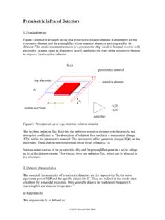
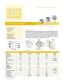
1 1/8 - 2011 ROHM Co., Ltd. All rights reserved. IC for Human Body Detector Amplifier for Pyroelectric Infrared Sensor BD9251FV Description BD9251FV is used for the human body detection application. Make to single-chip, easy to use then before. Power-saving in the best design. Reduce the standby power requirement of the device used always. Don t choose the mounting place by a space-saving. Features 1) Amplifier for Sensor output 2) Comparator for Sensor output 3) Built-in voltage regulator 4) Built-in moving detector Applications Lighting, Sensor Light, Security system, WEB camera, TV, PC display, Air Conditioner, Ventilation fan Absolute Maximum Ratings (Ta=25 C) Parameter Symbol Ratings UnitsSupply Voltage VDD V Power Dissipation Pd 440 1 mW Operating Temperature Topr -30 75 C Storage Temperature Tstg -55 125 C 1.
2 It reduces C then Ta 25 C. (On glass epoxy board of 70mm 70mm ) Operating Conditions Parameter Symbol Ratings UnitsConditions Min. Typ. Voltage VDD V A1P_IN Offset Voltage VA1P_IN_OFFSET- - V VDRAIN= This product doesn t design for protection radioactive rays. Note 2/8 BD9251FV - 2011 ROHM Co., Ltd. All rights reserved. Electric Characteristics (VDD= , Ta=25 C) Parameter Symbol Limits UnitsConditions Min. Typ. Current IDD - 300 400 uA Output no load DRAIN Output Voltage VDRAIN - V VDD , IDRAIN 100 A AMP1/AMP2 Input Voltage VIN - AMP1/AMP2 Gain AG - - 46 dB AMP1/AMP2 Unity Gain AUG - 1 - MHz AMP1 Input Offset Voltage VA1 OFF - - 10 mV AMP2 Output Offset Voltage VA2 OUT - - V A2_OUT Output Current (source) IA2 OUT1 20 30 - A A2_OUT Output Current (sink)
3 IA2 OUT2 20 200 - A D_OUT / T_OUT Output "H" Voltage VOH VDD V IOH=-1mA D_OUT / T_OUT Output "L" Voltage VOL 0 - V IOL=+1mA Technical Note 3/8 BD9251FV - 2011 ROHM Co., Ltd. All rights reserved. Electrical characteristic curves (Reference data) amp1/amp2 closed-loop-gain VDD= amp1/amp2 closed-loop-gain VDD=5V amp1/amp2 closed-loop-gain VDD=6V 0123- 50050100Ta [ C]DRAIN[V] Drain Voltage (source 100uA) Drain Voltage (Ta=25 C) 0123234567 VDD[V]DRAIN [V]-30 C25 C75 C05010015020025030035040023 456 78 VDD[V]IDD [uA]-30 C25 C75 + 01 + 02 + 03 + 04 + 05 + 06 + 07fr eq uency [H z]gain [dB]-30 C25 C75 +01 +02 +03 +04 +05 +06 +07fr eq uency [H z]gai n [dB]-30 C25 C75 +01 +02 +03 +04 +05 +06 +07fr eq uency [H z]gai n [dB]-30 C25 C75 C050100150200250300350400-50050100Ta[ C]IDD [uA] [uA]DRAIN[V] + 01 + 02 + 03 + 04 + 05 + 06fr eq uency [H z]RIPPLE REJECTION [dB] Drain Voltage PSRR (Ta=25 C)
4 VDD= + 01 + 02 + 03 + 04 + 05 + 06fr eq uency [H z]RIPPLE REJECTION [dB] Drain Voltage PSRR (Ta=25 C) VDD= + 01 + 02 + 03 + 04 + 05 + 06fr eq uency [H z]RIPPLE REJECTION [dB] Drain Voltage PSRR (Ta=25 C) VDD= 2 l oad [uF]war m _up_ti m e [us] l DRAIN VOLTAGE warm_up_time (Ta=25 C) IDD IDD Drain Voltage (source 100uA) Technical Note 4/8 BD9251FV - 2011 ROHM Co., Ltd. All rights reserved. D_OUT Output Low Voltage (sink 1mA) D_OUT Output High Voltage (source 1mA) Electrical characteristic curves (Reference data) Continued 01234567234 567 VDD [V]D_OUT [V]-30 C25 C75 C01234567234567 VDD [V]T_OUT [V]-30 C25 C75 T_OUT Output Low Voltage (sink 1mA) T_OUT Output High Voltage (source 1mA) AMP2 Output High Voltage (source 20uA) 01234567- 50050100Ta [ C]A2_OU T [V] AMP2 Output High Voltage (source 20uA) AMP2 Output Low Voltage (sink 20uA) AMP2 Output Low Voltage (source 20uA)
5 01234567234567 VDD [V]A2_OU T [V]-30 C25 C75 C01234567- 50050100Ta [ C]A2_OU T [V] 45 67 VDD [V]D_OUT [V]-30 C25 C75 C01234567234 567 VDD [V]T_OUT [V]-30 C25 C75 C01234567234567 VDD [V]A2_OU T [V]-30 C25 C75 CTechnical Note 5/8 BD9251FV - 2011 ROHM Co., Ltd. All rights reserved. Block Diagram/Application DSGC247k A1P_INDRAINVDDD_OUGNDA2_OUTA1N_INA2N_INA 1_OUT650k VoltageRegulatorPyroelectricsensorT_OUR1 C4R2C5C6R3C7C3+-350k +-A2P_DI-+ -+ 33k 33k REF_OUT COMP_INC1R5BD9251FV10k AMP1 AMP2 Please decide the constant after it confirms it enough examing the characteristic and the conditionof the Pyroelectric Sensor . Example of circuit constant C1=C2=C3 : 1uF R1=R3 : 47k C4=C6 : R2=R4 : C5=C7 : 15nF R5 : 220k C8 : 10uF PIN Description PIN No.
6 PIN Name Function Remarks 1 GND Ground 2 NC NC 3 DRAIN Power supply for Pyroelectric Infrared Sensor 4 A1P_IN Sensor input 5 A1N_IN Amp1 n-input 6 A1_OUT Amp1 output 7 A2P_DI Amp2 diode output 8 A2N_IN Amp2 n-input 9 A2_OUT Amp2 output, Analog output 10 REF_OUT Reference voltage (1/2 VDD) output 11 COMP_IN Comparator input 12 D_OUT Comparator output 13 T_OUT Moving detection output 14 VDD Power supply DSGC247k A1P_INDRAINVDDD_OUTGNDA2_OUTA1N_INA2N_IN A1_OUT650k VoltageRegulato rPyroelectricsensorT_OUTR1C4R2C5C6R3C7C3 +-350k +-A2P_DI-+ -+ 33k 33k REF_OUTCOMP_INC1R5BD9251FV10k AMP1 AMP2 Please decide the constant after it confirms it enough examing the characteristic and the conditionof the Pyroelectric Note 6/8 BD9251FV - 2011 ROHM
7 Co., Ltd. All rights reserved. Timing chart ( When using dual type pyro Sensor ) LeftRight LeftRight Time axis Time axisA1P_INA1P_IN(Pyro Sensor output) Pyro Sensor output)A2_OUT A2_OUT(Analog output) (Analog output)VREF_H sideVREF_H sideComparator output Comparator outputVREF_L side VREF_L sideComparator output Comparator outputD_OUT D_OUTT_OUT T_OUTVREF_HVREF_LPyro Sensor VREF_HVREF_LPyro Sensor LH HLSensor Part1 2 Sensor Part1 2 When using dual type pyro Sensor , it s possible to detect the direction of movement by checking the switch of T_out signal at D_out=H. Technical Note 7/8 BD9251FV - 2011 ROHM Co., Ltd. All rights reserved. Notes for use (1) Absolute maximum ratings Use of the IC in excess of absolute maximum ratings such as the applied voltage or operating temperature range may result in IC damage. Assumptions should not be made regarding the state of the IC (short mode or open mode) when such damage is suffered.
8 A physical safety measure such as a fuse should be implemented when use of the IC in a special mode where the absolute maximum ratings may be exceeded is anticipated. (2) GND potential Ensure a minimum GND pin potential in all operating conditions. (3) Short circuit mode between terminals and wrong mounting In order to mount the IC on a set PCB, pay thorough attention to the direction and offset of the ICs. Erroneous mounting can destroy the IC. Furthermore, if a short circuit occurs due to foreign matters entering between terminals or between the terminal and the power supply or the GND terminal, the IC can destroy. (4) Actions in strong magnetic field Use caution when using the IC in the presence of a strong magnetic field as doing so may cause the IC to malfunction. (5) Mutual impedance Use short and wide wiring tracks for the power supply and ground to keep the mutual impedance as small as possible.
9 Use a capacitor to keep ripple to a minimum. (6) About warm-up time Operation depends on a power-supply voltage and an external constant for time until stabilizing. Please confirm warm-up time enough when you use it. (7) PCB design considerations To reduce the noise from OUTPUT to INPUT , COMP_IN(11pin) and D_OUT(12pin) and T_OUT(13pin) lines away from Pyro Sensor and A1P_IN(4pin). Technical Note 8/8 BD9251FV - 2011 ROHM Co., Ltd. All rights reserved. Ordering part number B D 9 2 5 1 F V - E 2 Part No. Part No. Package FV: SSOP-B14 Packaging and forming specification E2: Embossed tape and reel Order quantity needs to be multiple of the minimum quantity.<Tape and Reel information>Embossed carrier tapeTapeQuantityDirection of feedThe direction is the 1pin of product is at the upper left when you hold reel on the left hand and you pull out the tape on the right hand2500pcsE2()Direction of feedReel1pin(Unit : mm) Notice - GE 2014 ROHM Co.
10 , Ltd. All rights reserved. Notice Precaution on using ROHM Products 1. Our Products are designed and manufactured for application in ordinary electronic equipments (such as AV equipment, OA equipment, telecommunication equipment, home electronic appliances, amusement equipment, etc.). If you intend to use our Products in devices requiring extremely high reliability (such as medical equipment (Note 1), transport equipment, traffic equipment, aircraft/spacecraft, nuclear power controllers, fuel controllers, car equipment including car accessories, safety devices, etc.) and whose malfunction or failure may cause loss of human life, bodily injury or serious damage to property ( Specific Applications ), please consult with the ROHM sales representative in advance. Unless otherwise agreed in writing by ROHM in advance, ROHM shall not be in any way responsible or liable for any damages, expenses or losses incurred by you or third parties arising from the use of any ROHM s Products for Specific Applications.