Transcription of BR24G64xxx-3 Series : Memory
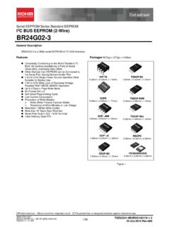
1 Product structure : Silicon monolithic integrated circuit This product has no designed protection against radioactive rays 1/ 34 TSZ02201-0R2R0G100220-1-2 2012 ROHM Co., Ltd. All rights reserved. TSZ22111 14 001 Serial EEPROM Series Standard EEPROM I2C BUS EEPROM (2-Wire) BR24G64-3 General Description BR24G64-3 is a 64 Kbit serial EEPROM of I2C BUS interface method Features Completely conforming to the world standard I2C BUS. All controls available by 2 ports of serial clock (SCL) and serial data (SDA) Other devices than EEPROM can be connected to the same port, saving microcontroller port to Single Power Source Operation most suitable for battery use to wide limit of operating voltage, possible FAST MODE 400 KHz operation Up to 32 Byte in Page Write Mode Bit Format 8K x 8 Self-timed Programming Cycle Low Current Consumption Prevention of Write Mistake WP (Write Protect) Function added Prevention of Write Mistake at Low Voltage 1 million write cycles 40 years data retention Noise filter built in SCL / SDA terminal Initial delivery state FFh Packages W(Typ) x D(Typ)
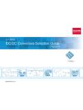
2 X H(Max) Figure 1. VSON008X2030 x x TSSOP-B8 x x SOP8 x x DIP-T8 x x TSSOP-B8J x x MSOP8 x x SSOP-B8 x x SOP- J8 x x Datasheet Datasheet 2/34 BR24G64-3 TSZ02201-0R2R0G100220-1-2 2012 ROHM Co., Ltd. All rights reserved. TSZ22111 15 001 Absolute Maximum Ratings (Ta=25 C) Parameter Symbol Rating Unit Remark Supply Voltage VCC to + V Power Dissipation Pd (SOP8) W Derate by / C when operating above Ta=25 C (SOP-J8) Derate by / C when operating above Ta=25 C (SSOP-B8) Derate by / C when operating above Ta=25 C (TSSOP-B8) Derate by / C when operating above Ta=25 C (TSSOP-B8J) Derate by / C when operating above Ta=25 C (MSOP8) Derate by / C when operating above Ta=25 C (VSON008X2030) Derate by / C when operating above Ta=25 C (DIP-T8)
3 Derate by / C when operating above Ta=25 C Storage Temperature Tstg -65 to +150 C Operating Temperature Topr -40 to +85 C Input Voltage / Output Voltage - to Vcc+ V The Max value of Input Voltage/Output Voltage is not over When the pulse width is 50ns or less, the Min value of Input Voltage/Output Voltage is Junction Temperature Tjmax 150 C Junction temperature at the storage condition Electrostatic discharge voltage (human body model) VESD -4000 to +4000 V Memory Cell Characteristics (Ta=25 C, Vcc= to ) Parameter Limit Unit Min Typ Max Write Cycles (1) 1,000,000 - - Times Data Retention (1) 40 - - Years (1) Not 100% TESTED Recommended Operating Ratings Parameter Symbol Rating Unit Power Source Voltage Vcc to V Input Voltage VIN 0 to Vcc DC Characteristics (Unless otherwise specified, Ta=-40 C to +85 C, Vcc= to ) Parameter Symbol Limit Unit Conditions Min Typ Max Input High Voltage1 VIH1 - Vcc+ V Vcc Input Low Voltage1 VIL1 (2) - + V Vcc Input High Voltage2 VIH2 - Vcc+ V Vcc< Input Low Voltage2 VIL2 (2) - + V Vcc< Output Low Voltage1 VOL1 - - V IOL= , Vcc (SDA) Output Low Voltage2 VOL2 - - V IOL= , Vcc< (SDA) Input Leakage Current ILI -1 - +1 A VIN=0 to Vcc Output Leakage Current ILO -1 - +1 A VOUT=0 to Vcc (SDA) Supply Current (Write)
4 ICC1 - - mA Vcc= , fSCL=400kHz, tWR=5ms, Byte write, Page write Supply Current (Read) ICC2 - - mA Vcc= , fSCL=400kHz Random read, current read, sequential read Standby Current ISB - - A Vcc= , SDA, SCL=Vcc A0,A1,A2=GND,WP=GND (2) When the pulse width is 50ns or less, it is Datasheet 3/34 BR24G64-3 TSZ02201-0R2R0G100220-1-2 2012 ROHM Co., Ltd. All rights reserved. TSZ22111 15 001 AC Characteristics (Unless otherwise specified, Ta=-40 C to +85 C, Vcc= to ) Parameter Symbol Limit Unit Min Typ Max Clock Frequency fSCL - - 400 kHz Data Clock High Period tHIGH - - s Data Clock Low Period tLOW - - s SDA, SCL (INPUT) Rise Time (1) tR - - s SDA, SCL (INPUT) Fall Time (1) tF1 - - s SDA (OUTPUT) Fall Time (1) tF2 - - s Start Condition Hold Time tHD:STA - - s Start Condition Setup Time tSU:STA - - s Input Data Hold Time tHD:DAT 0 - - ns Input Data Setup Time tSU:DAT 100 - - ns Output Data Delay Time tPD - s Output Data Hold Time tDH - - s Stop Condition Setup Time tSU.
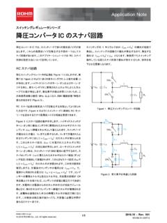
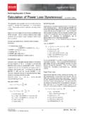
5 STO - - s Bus Free Time tBUF - - s Write Cycle Time tWR - - 5 ms Noise Spike Width (SDA and SCL) tI - - s WP Hold Time tHD:WP - - s WP Setup Time tSU:WP - - s WP High Period tHIGH:W P - - s (1) Not 100% TESTED. Condition Input data level:VIL= Vcc VIH= Vcc Input data timing reference level: Vcc Output data timing reference level: Vcc Rise/Fall time : 20ns Serial Input / Output Timing Input read at the rise edge of SCL Data output in sync with the fall of SCL Figure 2-(a). Serial Input / Output Timing Figure 2-(b). Start-Stop Bit Timing Figure 2-(c). Write Cycle Timing Figure 2-(d). WP Timing at Write Execution Figure 2-(e). WP Timing at Write Cancel SCL SDA (input) SDA (output) tR tF1 tHIGH tSU:DAT tLOW tHD:DAT tDH tPD tBUF tHD:STA 70% 30% 70% 70% 30% 70% 70% 30% 30% 70% 70% 30% 70% 70% 70% 70% 30% 30% 30% 30% tF2 70% 70% tSU:STA tHD:STA START condition tSU:STO STOP condition 30% 30% 70% 70% SDA SCL D0 ACK tWR write data (n-th address) START condition STOP condition 70% 70% SDA SCL DATA(1) DATA(n) ACK tWR 70% 70% STOP condition tHD:WP tSU:WP 30% 70% SDA SCL WP DATA(1) D0 D1 ACK DATA(n) ACK tHIGH:WP 70% 70% tWR 70% SDA SCL WP Datasheet 4/34 BR24G64-3 TSZ02201-0R2R0G100220-1-2 2012 ROHM Co.
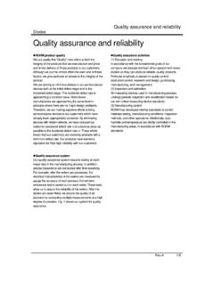
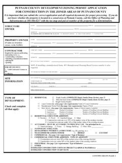
6 , Ltd. All rights reserved. TSZ22111 15 001 Block Diagram Figure 3. Block Diagram Pin Configuration (TOP VIEW) Pin Descriptions Terminal Name Input/ Output Descriptions A0 Input Slave address setting* A1 Input Slave address setting* A2 Input Slave address setting* GND - Reference voltage of all input / output, 0V SDA Input/ output Serial data input serial data output SCL Input Serial clock input WP Input Write protect terminal VCC - Connect the power source. *A0, A1 and A2 are not allowed to use as open. 8 7 6 5 4 3 2 1 SDA SCL WP V CC GND A2 A1 A0 Address Decoder Word Address Register Data Register Control circuit High Voltage Generating circuit Power Source Voltage Detection 8bit ACK START STOP 13bit 64 Kbit EEPROM Array 2 5 6 VCC SCL GND BR24G64-3 1 3 4 7 8 WP SDA A2 A1 A0 Datasheet 5/34 BR24G64-3 TSZ02201-0R2R0G100220-1-2 2012 ROHM Co.
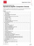
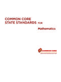
7 , Ltd. All rights reserved. TSZ22111 15 001 Figure 6. Output Low Voltage1 vs Output Low Current (Vcc= ) Figure 7. Output Low Voltage2 vs Output Low Current (Vcc= ) Figure 4. Input High Voltage1,2 vs Supply Voltage (A0, A1, A2, SCL, SDA, WP) Figure 5. Input Low Voltage1,2 vs Supply Voltage (A0, A1, A2, SCL, SDA, WP) Typical Performance Curves Low Current : IOL(mA)Output Low Voltage1: VOL1(V)SPECTa=-40 CTa= 25 CTa= 85 C01234560123456 Supply Voltage : Vcc(v)Input Low Voltage1,2 : VIL1,2(V)Ta=-40 CTa= 25 CTa= 85 CSPEC01234560123456 Supply Voltage : Vcc(v)Input High Voltage1,2 : VIH1,2(V)Ta=-40 CTa= 25 CTa= 85 Low Current : IOL(mA)Output Low Voltage2: VOL2(V)Ta=-40 CTa= 25 CTa= 85 CSPECD atasheet 6/34 BR24G64-3 TSZ02201-0R2R0G100220-1-2 2012 ROHM Co.
8 , Ltd. All rights reserved. TSZ22111 15 001 Figure 11. Supply Current (Read) vs Supply Voltage (fSCL=400kHz) Figure 8. Input Leakage Current vs Supply Voltage (A0, A1, A2, SCL, WP) Figure 9. Output Leakage Current vs Supply Voltage (SDA) Figure 10. Supply Current (Write) vs Supply Voltage (fSCL=400kHz) Typical Performance Curves continued Voltage : Vcc(v)Input Leakage Current : I LI ( A)Ta=-40 CTa= 25 CTa= 85 Voltage : Vcc(v)Output Leakage Current : I LO( A)Ta=-40 CTa= 25 CTa= 85 Voltage : Vcc(v)Supply Current (Write) : ICC1(mA)Ta=-40 CTa= 25 CTa= 85 Voltage : Vcc(v)Supply Current (Read) : ICC2(mA)SPECTa=-40 CTa= 25 CTa= 85 CDatasheet 7/34 BR24G64-3 TSZ02201-0R2R0G100220-1-2 2012 ROHM Co.
9 , Ltd. All rights reserved. TSZ22111 15 001 Figure 13. Clock Frequency vs Supply Voltage Figure 14. Data Clock High Period vs Supply Voltage Figure 12. Standby Current vs Supply Voltage Figure 15. Data Clock Low Period vs Supply Voltage Typical Performance Curves continued Voltage : Vcc(v)Clock Frequency : fSCL(kHz)SPECTa=-40 CTa= 25 CTa= 85 Voltage : Vcc(v)Standby Current : I SB ( A)SPECTa=-40 CTa= 25 CTa= 85 Voltage : Vcc(v)Data Clock High Period : t HIGH( s)SPECTa=-40 CTa= 25 CTa= 85 Voltage : Vcc(v)Data Clock Low Period : t LOW( s)SPECTa=-40 CTa= 25 CTa= 85 CDatasheet 8/34 BR24G64-3 TSZ02201-0R2R0G100220-1-2 2012 ROHM Co., Ltd. All rights reserved.
10 TSZ22111 15 001 Figure 17. Start Condition Setup Time vs Supply Voltage Figure 18. Input Data Hold Time vs Supply Voltage (HIGH) Figure 16. Start Condition Hold Time vs Supply Voltage Figure 19. Input Data Hold Time vs Supply Voltage (LOW) Typical Performance Curves continued Voltage : Vcc(v)Start Condition Hold Time : t HD:STA( s)SPECTa=-40 CTa= 25 CTa= 85 Voltage : Vcc(v)Start Condition Setup Time : t SU:STA ( s)SPECTa=-40 CTa= 25 CTa= 85 C-200-150-100-500500123456 Supply Voltage : Vcc(v)Input Data Hold Time : t HD:DAT (ns)SPECTa=-40 CTa= 25 CTa= 85 C-200-150-100-500500123456 Supply Voltage : Vcc(v)Input Data Hold Time : t HD:DAT(ns)SPECTa=-40 CTa= 25 CTa= 85 CDatasheet 9/34 BR24G64-3 TSZ02201-0R2R0G100220-1-2 2012 ROHM Co.