Transcription of Datasheet 4ch White LED Driver with Buck Boost …
1 Datasheet 4ch White LED Driver with buck - Boost (40 LED Maximum). BD81A44 MUV-M / BD81A44 EFV-M. General Description Key Specifications BD81A44 MUV-M/EFV-M is a White LED Driver with the capability of Operating Input Voltage Range to 35 V. withstanding high input voltage (35V Max). This Driver has 4ch Output LED Current Accuracy constant-current drivers integrated in 1-chip, where each channel DC/DC Oscillation Frequency 200 to 2200kHz can draw up to 120mA (Max), which is also suitable for high illumination LED drive. Furthermore, a buck - Boost current mode Operating Temperature Range -40 to +125 . DC/DC controller is also integrated to achieve stable operation LED Maximum Output Current 120mA/ch during power voltage fluctuation. Light modulation (10,000:1 PWM min pulse width @100Hz dimming function) is possible by PWM input.
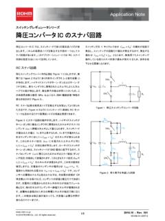
2 Features Package(s) W(Typ) x D(Typ) x H(Max). Integrated buck - Boost current mode DC/DC controller VQFN28SV5050 HTSSOP-B28. Integrated 4ch current Driver for LED drive (BD81A44 MUV-M) (BD81A44 EFV-M). 10,000:1 PWM dimming @100Hz External switching frequency synchronization W(Typ) D(Typ) H(Max) W(Typ) D(Typ) H(Max). Built-In protection function (UVLO, OVP, OCP, SCP) LED abnormality detection function (Open/Short). Integrated VOUT discharge function ( buck - Boost or buck structure limitation). AEC-Q100 Qualified (Note 1). (Note 1) Grade1. Application For Display audio, CID, Cluster, HUD. Small and Medium type LCD Panels for Automotive use. Typical Application Circuit VCC CIN. CREG. COUT. VREG VDISC. OVP. VCC. CS. EN. BOOT. OUTH. SW. SYNC. RT. OUTL. RRT. DGND. COMP. RPC BD81A44 MUV-M /. CPC. BD81A44 EFV-M LED1.
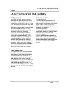
3 SS. LED2. CSS. LED3. LED4. PWM. ISET. PGND. RISET. VREG. FAIL1. GND. FAIL2. SHDETEN LEDEN1 LEDEN2. Figure 1. buck - Boost Application Circuit Product structure Silicon monolithic integrated circuit This product has no designed protection against radioactive rays 2016 ROHM Co., Ltd. All rights reserved. 1/35 TSZ02201-0T3T0C600060-1-2. TSZ22111 15 001 BD81A44 MUV-M/EFV-M. Pin Description Pin Configuration VQFN28SV5050 (Top view). VQFN28 HTSSOP Terminal SHDETEN. FAIL2 SV5050 Name Function FAIL1. SYNC. -B28. PWM. GND. RT. 1 11 LEDEN1 LED output pin enable terminal 1. 28 27 26 25 24 23 22. 2 12 LEDEN2 LED output pin enable terminal 2. LEDEN1 1 21 COMP 3 13 LED1 LED output terminal 1. LEDEN2 2 20 SS 4 14 LED2 LED output terminal 2. LED1 3 19 VCC 5 15 LED3 LED output terminal 3. LED2 4 18 CS 6 16 LED4 LED output terminal 4.
4 EN. 7. LED3 5 17. Thermal PAD. 17 OVP Over-voltage detection terminal LED4 6 16 VREG. 8 18 ISET LED output current setting terminal OVP 7 15 BOOT. 9 19 PGND LED output GND terminal 8 9 10 11 12 13 14. 10 20 OUTL Low side FET gate terminal PGND. DGND. VDISC. ISET. OUTL. 11. SW. OUTH. 21 DGND DC/DC output GND terminal 12 22 VDISC Output voltage discharge terminal 13 23 SW High side FET source terminal HTSSOP-B28 (Top view) 14 24 OUTH High side FET gate terminal VCC. 15 25 BOOT High side FET Driver power supply terminal 1 28 CS. SS 2 27 EN 16 26 VREG Internal constant voltage COMP. RT. 3. 4. 26. 25. VREG. BOOT. 17 27 EN Enable terminal SYNC 5 24 OUTH 18 28 CS DC/DC current sense terminal SHDETEN. GND. 6. 7. 23. 22. SW. VDISC. 19 1 VCC Input power supply terminal PWM 8 21 DGND 20 2 SS Soft Start Capacitor connection FAIL1.
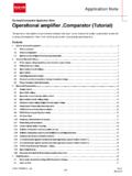
5 FAIL2. 9. 10. 20. 19. OUTL. PGND. 21 3 COMP ERR AMP output LEDEN1 11 18 ISET 22 4 RT Oscillation Frequency-setting resistor input LEDEN2. LED1. 12 Thermal PAD 17 OVP. 23 5 SYNC External synchronization input terminal 13 16 LED4. LED2 14 15 LED3 24 6 SHDETEN Short detection enable signal 25 7 GND Small signal GND terminal Figure 2. Pin Configuration 26 8 PWM PWM light modulation input terminal 27 9 FAIL1 Failure signal output terminal 28 10 FAIL2 LED open/short detection output signal Thermal Back side thermal PAD. - - PAD (Please connect to GND). Block Diagram VREG VDISC. OVP. OVP. UVLO TSD. OVP10. VCC. VREG OCP CS.. Timer EN PWM Latch FAIL1. BOOT. Control Logic OUTH. DRV. CTL SW.. SYNC PWM. SLOPE . OSC VREG. RT. OUTL. DGND. ERR AMP.. COMP .. OCP OVP LED1. SS LED2. SS. LED3. Current Driver PWM LED4.
6 PGND. ISET Open Short Detect ISET. Open Det Timer Latch Short Det FAIL2. Figure 3. Internal Block Diagram GND. SHDETEN LEDEN1 LEDEN2. 2016 ROHM Co., Ltd. All rights reserved. 2/35 TSZ02201-0T3T0C600060-1-2. TSZ22111 15 001 BD81A44 MUV-M/EFV-M. Description of Blocks 1. Voltage Reference (VREG). 5V (Typ) is generated from the VCC Input Voltage (when at EN=High). This voltage (VREG) is used as power supply of internal circuit and when fixing the pins outside of the IC at a high voltage, as well. The UVLO protection is integrated in V REG. The circuit starts to operate at VCC (Typ) and VREG= (Typ) and stops when at VCC (Typ) or VREG (Typ). For release/cancellation condition and detection condition, please refer to Table 2 on page 11. Connect a ceramic capacitor (CREG) to VREG terminal for phase compensation.
7 Creg range is to and recommend value is If the CREG. is not connected, the operation of circuit will be notably unstable. 2. Constant Current Driver Table1. LED Control Logic LEDEN1 LEDEN2 LED1 LED2 LED3 LED4. L L ON ON ON ON. H L ON ON ON OFF. L H ON ON OFF OFF. H H ON OFF OFF OFF. If less than four constant-current drivers are used, please make the LED1~4 terminal open' while the output OFF' by LEDEN1 and LEDEN2 terminal. The truth table for these pins is shown above. If the unused constant-current Driver output will be set open without the process of LEDEN1,2 terminals, the open detection' will be activated. The LEDEN1, 2 terminals is pulled down internally in the IC and it is low at open' condition. They should be connected to VREG terminal or fixed to logic HIGH when in use. (1) Output Current Setting (RISET).
8 ILED vs RISET. 120. 110. 100. 90. 80. ILED [mA]. 70. 60. 50. 40. 30. 20. 40 60 80 100 120 140 160 180 200 220 240. RISET[k ]. Figure 4. ILED vs RISET. The Output Current ILED can be obtained by the following equation: [ ] = ( [ ]) 5000. RISET operating range is 41kohm to 250kohm. It can not change the RISET value in the operation. This IC has ISET-GND short protection that protect LED element from over current when ISET and GND is short. If the RISET. value is under , the IC detects ISET-GND short and LED current becomes off. 2016 ROHM Co., Ltd. All rights reserved. 3/35 TSZ02201-0T3T0C600060-1-2. TSZ22111 15 001 BD81A44 MUV-M/EFV-M. <Caution of LED current setting>. If the output current ILED is set to >100mA/ch, the stability of LED current within specified operating temperature range will decrease.
9 LED current supply value will depends on the amount of ripple in output voltage (VOUT). The figure below shows the temperature and the possible LED current maximum value settings, please adjust the ripple voltage in such a way that the LED. current value setting will fall within the range as shown on the graph below. ( VOUT Output Ripple Voltage) Please refer , there is the detail information of VOUT ripple voltage. Ta vs ILED. 120. ILED [mA]. 110. 100 VOUT=50mV. VOUT=100mV. 90 VOUT=200mV. 80. -40 -25 -10 5 20 35 50 65 80 95 110 125. Ta [ ]. Figure 5. Temperature (Ta) vs Output LED Current (ILED). (2) PWM Intensity Control 500ns/div 1ms/div PWM PWM. (2V/div) (2V/div). ILED. (50mA/div) ILED. (50mA/div). Figure 6. PWM=150Hz, Duty= , ILED Waveform Figure 7. PWM=150Hz, Duty= , ILED Waveform The current Driver ON/OFF is controlled by PWM terminal.
10 The duty ratio of PWM terminal becomes duty ratio of ILED. If don't use PWM dimming, please set the PWM terminal to HIGH. Output light intensity is greatest at 100% input 3. buck - Boost DC/DC Controller (1) Number of LED in Series Connection In this IC, the output voltage of the DC/DC converter (VOUT) is controlled by LED cathode voltage (LED1 4 terminal voltage) becomes (Typ). When two or more LED are operating at the same time, the LED terminal voltage that connects the highest LED Vf row is held at (Typ). Then the voltages of other LED terminal will increased only LED VF. tolerance. Please decide LED VF tolerance by using the description as shown below: LED series number x LED VF tolerance voltage < Short Detection Voltage (Min) LED Control Voltage (Max). (2) Over Voltage Protection (OVP).