Transcription of Analysis of the Sallen-Key Architecture (Rev. B)
1 AnalysisoftheSallen KeyArchitectureJuly 1999 Revised September 2002 Mixed Signal ProductsApplicationReportSLOA024 BIMPORTANT NOTICET exas instruments Incorporated and its subsidiaries (TI) reserve the right to make corrections, modifications,enhancements, improvements, and other changes to its products and services at any time and to discontinueany product or service without notice. Customers should obtain the latest relevant information before placingorders and should verify that such information is current and complete. All products are sold subject to TI s termsand conditions of sale supplied at the time of order warrants performance of its hardware products to the specifications applicable at the time of sale inaccordance with TI s standard warranty.
2 Testing and other quality control techniques are used to the extent TIdeems necessary to support this warranty. Except where mandated by government requirements, testing of allparameters of each product is not necessarily assumes no liability for applications assistance or customer product design. Customers are responsible fortheir products and applications using TI components. To minimize the risks associated with customer productsand applications, customers should provide adequate design and operating does not warrant or represent that any license, either express or implied, is granted under any TI patent right,copyright, mask work right, or other TI intellectual property right relating to any combination, machine, or processin which TI products or services are used.
3 Information published by TI regarding third party products or servicesdoes not constitute a license from TI to use such products or services or a warranty or endorsement of such information may require a license from a third party under the patents or other intellectual propertyof the third party, or a license from TI under the patents or other intellectual property of of information in TI data books or data sheets is permissible only if reproduction is withoutalteration and is accompanied by all associated warranties, conditions, limitations, and notices. Reproductionof this information with alteration is an unfair and deceptive business practice. TI is not responsible or liable forsuch altered of TI products or services with statements different from or beyond the parameters stated by TI for thatproduct or service voids all express and any implied warranties for the associated TI product or service andis an unfair and deceptive business practice.
4 TI is not responsible or liable for any such Address: texas InstrumentsPost Office Box 655303 Dallas, texas 75265 Copyright 2002, texas instruments Incorporatediii Analysis of the Sallen-Key ArchitectureContents1 Introduction1.. 2 Generalized Circuit Analysis2.. Gain Block Diagram2.. Ideal Transfer Function3.. 3 Low-Pass Circuit4.. Simplification 1: Set Filter Components as Ratios5.. Simplification 2: Set Filter Components as Ratios and Gain = 15.. Simplification 3: Set Resistors as Ratios and Capacitors Equal5.. Simplification 4: Set Filter Components Equal5.. Nonideal Circuit Operation6.. Simulation and Lab Data6.. 4 High-Pass Circuit9.. Simplification 1: Set Filter Components as Ratios10.. Simplification 2: Set Filter Components as Ratios and Gain=110.
5 Simplification 3: Set Resistors as Ratios and Capacitors Equal10.. Simplification 4: Set Filter Components as Equal10.. Nonideal Circuit Operation11.. Lab Data11.. 5 Summary and Comments About Component Selection13.. FiguresivSLOA024 BList of Figures1 Basic Second Order Low-Pass Filter1.. 2 Unity Gain Sallen-Key Low-Pass Filter1.. 3 Generalized Sallen-Key Circuit2.. 4 Gain-Block Diagram of the Generalized Sallen-Key Filter3.. 5 Low-Pass Sallen-Key Circuit4.. 6 Nonideal Effect of Amplifier Output Impedance and Transfer Function6.. 7 Test Circuits7.. 8 Effect of Output Impedance8.. 9 High-Pass Sallen-Key Circuit9.. 10 Model of High-Pass Sallen-Key Filter Above fc11.. 11 High-Pass Sallen-Key Filter Using THS300112.. 12 Frequency Response of High-Pass Sallen-Key Filter Using THS300112.
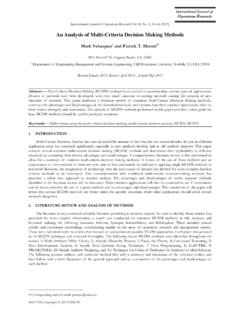
6 1 Analysis of the Sallen-Key ArchitectureJames KarkiABSTRACTThis application report discusses the Sallen-Key Architecture . The report gives a generaloverview and derivation of the transfer function, followed by detailed discussions oflow-pass and high-pass filters, including design information, and ideal and non-idealoperation. To illustrate the limitations of real circuits, data on low-pass and high-passfilters using the texas instruments THS3001 is included. Finally, component selection IntroductionFigure 1 shows a two-stage RC network that forms a second order low-pass filter is limited because its Q is always less than 1/2. With R1=R2 and C1=C2,Q=1/3. Q approaches the maximum value of 1/2 when the impedance of thesecond RC stage is much larger than the first.
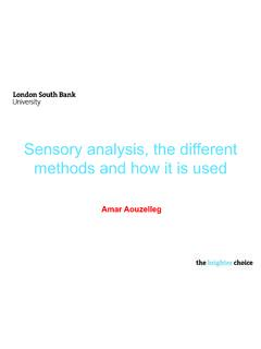
7 Most filters require Qs larger than1/2.()()11C1R1C2R2C1Rs1C2R2C1Rs1 ViVo2++++=VOC1R2 VIC2R1 Figure 1. Basic Second Order Low-Pass FilterLarger Qs are attainable by using a positive feedback amplifier. If the positivefeedback is controlled localized to the cut-off frequency of the filter almost anyQ can be realized, limited mainly by the physical constraints of the power supplyand component tolerances. Figure 2 shows a unity gain amplifier used in thismanner. Capacitor C2, no longer connected to ground, provides a positivefeedback path. In 1955, R. P. Sallen and E. L. Key described these filter circuits,and hence they are generally known as Sallen-Key + Figure 2. Unity Gain Sallen-Key Low-Pass FilterThe operation can be described qualitatively: At low frequencies, where C1 and C2 appear as open circuits, the signal issimply buffered to the output.
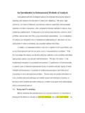
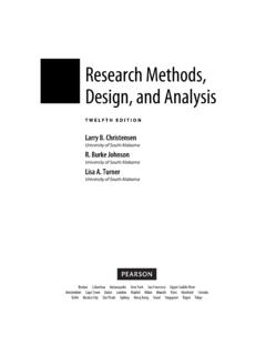
8 At high frequencies, where C1 and C2 appear as short circuits, the signal isshunted to ground at the amplifier s input, the amplifier amplifies this input toits output, and the signal does not appear at Vo. Near the cut-off frequency, where the impedance of C1 and C2 is on the sameorder as R1 and R2, positive feedback through C2 provides Q enhancementof the Circuit Analysis2 SLOA024B2 Generalized Circuit AnalysisThe circuit shown in Figure 3 is a generalized form of the Sallen-Key circuit,where generalized impedance terms, Z, are used for the passive filtercomponents, and R3 and R4 set the pass band + Figure 3. Generalized Sallen-Key CircuitTo find the circuit solution for this generalized circuit, find the mathematical relationshipsbetween Vi, Vo, Vp, and Vn, and construct a block at Vf:Vf 1Z1)1Z2)1Z4 +Vi 1Z1 )Vp 1Z2 )Vo 1Z4 KCL at Vp:Vp 1Z2)1Z3 +Vf 1Z2 Vf+Vp 1)Z2Z3 Substitute Equation (2) into Equation (1) and solve for Vp:Vp+Vi Z2Z3Z4Z2Z3Z4)Z1Z2Z4)Z1Z2Z3)Z2Z2Z4)Z2Z2Z1 )Vo Z1Z2Z3Z2Z3Z4)Z1Z2Z4)Z1Z2Z3)Z2Z2Z4)Z2Z2Z1 KCL at Vn:Vn 1R3)1R4 +Vo 1R4 Vn+Vo R3R3)R4 Gain Block DiagramBy letting: a(f) = the open-loop gain of the amplifier, b+ R3R3)R4 ,c+Z2Z3Z4Z2Z3Z4)Z1Z2Z4)Z1Z2Z3)Z2Z2Z4)Z2Z 2Z1,d+Z1Z2Z3Z2Z3Z4)Z1Z2Z4)Z1Z2Z3)Z2Z2Z4) Z2Z2Z1,and Ve = Vp Vn, the generalized Sallen-Key filter circuit is represented ingain-block form as shown in Figure 4.
9 (1)(2)(3)(4)Generalized Circuit Analysis3 Analysis of the Sallen-Key ArchitectureVea(f)VObVIcd+ +Figure 4. Gain-Block Diagram of the Generalized Sallen-Key FilterFrom the gain-block diagram the transfer function can be solved easily byobserving, Vo = a(f)Ve and Ve = cVi + dVo bVo. Solving for the generalizedtransfer function from gain block Analysis gives:VoVi+ cb 11)1a f b*db Ideal Transfer FunctionAssuming a(f)b is very large over the frequency of operation, 1a(f)b[0, the idealtransfer function from gain block Analysis becomes:VoVi+ cb 11*db By letting 1b+K, c+N1D, and d+N2D, where N1, N2, and D are thenumerators and denominators shown above, the ideal equation can be rewrittenas:VoVi+ KDN1*K@N2N1 . Plugging in the generalized impedance terms gives theideal transfer function with impedance terms:VoVi+KZ1Z2Z3Z4)Z1Z3)Z2Z3)Z1 1*K Z4)1(5)(6)(7)Low-Pass Circuit4 SLOA024B3 Low-Pass CircuitThe standard frequency domain equation for a second order low-pass filter is:HLP+K* ffc 2)jfQfc)1 Where fc is the corner frequency (note that fc is the breakpoint between the passband and stop band, and is not necessarily the 3 dB point) and Q is the qualityfactor.]
10 When f<<fc Equation (8) reduces to K, and the circuit passes signalsmultiplied by a gain factor K. When f=fc, Equation (8) reduces to jKQ, and signalsare enhanced by the factor Q. When f>>fc, Equation (8) reduces to *K fcf 2, andsignals are attenuated by the square of the frequency ratio. With attenuation athigher frequencies increasing by a power of 2, the formula describes a secondorder low-pass 5 shows the Sallen-Key circuit configured for low-pass:Z1+R1, Z2+R2, Z3+1sC1,Z4+1sC2, and K+1) + Figure 5. Low-Pass Sallen-Key CircuitFrom Equation (7), the ideal low-pass Sallen-Key transfer function is:VoVi(Ip)+Ks2(R1R2C1C2))s(R1C1)R2C1)R1 C2(1*K)))1By lettings+j2pf, fc+12pR1R2C1C2 , and Q+R1R2C1C2 R1C1)R2C1)R1C2(1*K),equation (9) follows the same form as Equation (8).