Transcription of APC Smart-UPS
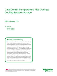
1 990-1352A 11/2003 User Manual EnglishAPC Smart-UPS 2200 VA 120/230 Vac 3000 VA 100/120/208/230 Vac 2U Rack Mount uninterruptible power supply 1 Introduction The APC uninterruptible power supply (UPS) is designed to prevent blackouts, brownouts, sags, and surges from reaching your equipment. The uninterruptible power supply (UPS) filters small util-ity line fluctuations and isolates your equipment from large disturbances by internally disconnecting from the utility line. The UPS provides continuous power from its internal battery until the utility line returns to safe levels or the battery is fully discharged.
2 1: INSTALLATION Unpack Read the Safety Guide before installing the UPS. The User Manual and Safety Guide are acces-sible on the supplied User Manuals CD and on the APC web site, Inspect the UPS upon receipt. Notify the carrier and dealer if there is damage. The packaging is recyclable; save it for reuse or dispose of it properly. Check the package contents: UPS Front bezel Rail kit UPS literature kit containing: Smart-UPS User Manuals CD 120/208/230 V Models Only: PowerChute CD, Serial and USB communication cables Product documentation, safety and warranty information Rack mounting brackets EPO Connector Hardware 230 V Models Only: Input power cord Alternate input power cord UK customers Utility connector plug IEC Jumper cords Rail Installation Install the rails following the instructions in the rail kit.
3 Placement of the UPS The UPS is heavy. Select a location sturdy enough to handle the weight. Do not operate the UPS in excessive dust or in temperature and humidity outside the specified limits. PLACEMENT 2 Mount the UPS in a Rack Your UPS model may vary from the examples depicted in this manual. n Install brackets as shown, or at a 5 in ( cm) setback. o Remove the battery module to lighten the UPS during installation. Note: The module is heavy. p Install the UPS at or near the bottom of the rack. q Reinstall the battery module. r Connect the battery module. s Attach the front bezel. 3 Connect Equipment and power to the UPS Startup 1.
4 Connect equipment to the UPS. A laser printer draws significantly more power than other types of equipment and may overload the UPS. 2. Add optional accessories to the smart -Slot. 3. Plug the UPS into a two-pole, three-wire, grounded receptacle only. Avoid using extension cords. 230 V model: The power cord is supplied in the UPS cable kit. The TVSS ground, located on the rear panel of the UPS must be connected prior to connecting the utility power . 4. 120 V model: Check the site wiring fault LED located on the rear panel. It will be illuminated if the UPS is plugged into an improperly wired utility power outlet, (see Troubleshooting).
5 5. Turn on all connected equipment. To use the UPS as a master on/off switch, be sure all con-nected equipment is on. 6. Press the button on the front panel to power the UPS. The battery charges to 90% capacity during the first four hours of normal operation. Do not expect full battery run capability during this initial charge period. 7. For optimal computer system security, install PowerChute Smart-UPS monitoring software. Rear Panels 100/120 V 208 V 230 V 4 Basic Connectors Serial Port USB Port TVSS Screw Use only interface kits approved by APC. Use only the supplied cable to connect to the Serial Port.
6 A standard serial interface cable is incompatible with the UPS. Serial and USB Ports cannot be used simultaneously. The UPS features a transient voltage surge-suppression (TVSS) screw for connecting the ground lead on surge suppression devices such as telephone and network line protectors. Prior to connecting grounding cable, disconnect the UPS from utility power . Emergency power Off The Emergency power Off (EPO) feature is user configurable. EPO provides immediate de-energizing of connected equipment from a remote location, without switching to battery operation. 1. Use the EPO connector supplied with the UPS. 2. Use a normally-open contact to connect the +24 terminal to the IN terminal, (see diagram).
7 3. Wire the four-pin connector to the EPO system. EPO Port (located on rear panel) EPO Connector The EPO interface is a Safety Extra Low Voltage (SELV) circuit. Connect it only to other SELV circuits. The EPO interface monitors circuits that have no determined voltage potential. Such closure circuits may be provided by a switch or relay properly isolated from the utility. To avoid damage to the UPS, do not connect the EPO interface to any circuit other than a closure type circuit. Use one of the following cable types to connect the UPS to the EPO switch: CL2: Class 2 cable for general use CL2P: Plenum cable for use in ducts, plenums, and other spaces used for environmental air.
8 CL2R: Riser cable for use in a vertical run in a floor to floor shaft. CLEX: Limited use cable for use in dwellings and for use in raceways. For installation in Canada: Use only CSA certified, type ELC (extra-low voltage control cable). +24 IN 5 2: OPERATION Front Display Panel INDICATOR DESCRIPTION Online The UPS is supplying utility power to the connected equipment (see Troubleshoot-ing). AVR Trim The UPS is compensating for a high utility voltage. AVR Boost The UPS is compensating for a low utility voltage. On Battery The UPS is supplying battery power to the connected equipment. Overload The connected loads are drawing more than the UPS power rating, (see Trouble-shooting).
9 Replace Battery/ Battery Discon-nected The battery is disconnected or must be replaced, (see Troubleshooting). FEATURE FUNCTION power On Press this button to turn on the UPS, (read on for additional capabilities). power Off Press this button to turn off the UPS. 6 FEATURE FUNCTION Self-Test Automatic: The UPS performs a self-test automatically when turned on, and every two weeks thereafter, (by default). During the self-test, the UPS briefly operates the connected equipment on battery. Manual: Press and hold the button for a few seconds to initiate the self-test. Cold Start 208/120/230 V models Only When there is no utility power and the UPS is off, the cold start feature will switch the UPS and connected equipment onto battery power , (see Troubleshooting).
10 Diagnostic Utility Voltage The UPS has a diagnostic feature that displays the utility voltage. The UPS starts a self-test as part of this procedure. The self-test does not af-fect the voltage display. Press and hold the button to view the utility voltage bar graph display. After a few seconds, this five-LED battery charge display on the right of the front panel will show the utility input voltage. Refer to the figure at left for the voltage reading, (values are not listed on the UPS). The display indicates the voltage is between the displayed value on the list and the next higher value, (see Troubleshooting). Battery Operation The UPS switches to battery operation automatically if the utility power fails.