Transcription of APC Smart-UPSfi SC
1 990-1851D 03/2007 User Manual English APC smart -UPS SC 1000/1500 VA 110/120/230 Vac Tower/Rack-Mount 2U uninterruptible power supply 1 Introduction The APC uninterruptible power supply (UPS) is designed to prevent blackouts, brownouts, sags, and surges from reaching your equipment. The uninterruptible power supply (UPS) filters small util-ity line fluctuations and isolates your equipment from large disturbances by internally disconnecting from the utility line. The UPS provides continuous power from its internal battery until the utility line returns to safe levels or the battery is fully discharged.
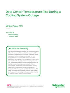
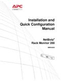
2 1: INSTALLATION Unpack Attention: Read the safety instruction sheet before installation. Inspect the UPS upon receipt. Notify the carrier and dealer if there is damage. The packaging is recyclable; save it for reuse or dispose of it properly. Check the package contents: Attention: The UPS comes with battery disconnected. ! UPS ! UPS literature kit containing: ! Product documentation, safety and warranty information ! smart -UPS User Manuals CD ! PowerChute Business Edition CD ! Serial communication cable ! Rack-mounting hardware ! 230 V models: Two jumper cables Position the UPS 2 Tower Configuration Note: Illustrations in this document may appear different than the actual hardware.
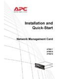
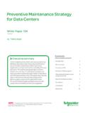
3 " # $ % Mount the UPS in a Two-Post Rack " # Remove battery bracket screws, battery bracket, and battery. 3 $ % Note: For information on the four-post rack-mounting kit, see & Reinstall battery, battery bracket, and screws. ' 4 2: START UP Connect Equipment to the UPS Rear Panels 110/120 V: 230 V: Note: A laser printer draws significantly more power than other types of equipment and may overload the UPS. Connect the UPS to the Network (if Applicable) Network Connectors Serial Port Modem/Telephone/Fax Ports Network Surge Suppression Ports Use only interface kits approved by APC.
4 Use only the supplied cable to connect to the Serial Port. A standard serial interface cable is incom-patible with the UPS. The UPS features modem/telephone/fax surge suppression ports. Connect a single mo-dem/telephone/fax line into the RJ-11 modem/telephone/fax surge protection IN jack on the back of the UPS. Use telephone cabling (not supplied) to connect the OUT jack to a modem/telephone/fax port. The UPS also features network surge suppression. Connect a single line 10 Base-T/ 100 Base-Tx network cable into the RJ-45 network surge protection IN jack on the back of the UPS.
5 Use network cabling (not supplied) to connect the OUT jack to a network port. 5 Start the UPS 1. Plug the UPS into a two-pole, three-wire, grounded receptacle only. Avoid using extension cords. 110/120 V models: The power cord is attached to the UPS. The input plug is a NEMA 5-15P. 230 V models: The power cord is supplied in the UPS literature kit. 2. 110/120 V models: Check the site wiring fault LED located on the rear panel. It will be illu-minated if the UPS is plugged into an improperly wired utility power outlet (see Troubleshoot-ing).
6 3. Turn on all connected equipment. To use the UPS as a master on/off switch, be sure all con-nected equipment is on. 4. Press the button on the front panel to power the UPS. Note: The battery charges fully during the first four hours of normal operation. Do not expect full battery run capability during this initial charge period. Refer to for on battery runtimes. 5. For optimal computer system protection, install PowerChute Business Edition management soft-ware to fully configure UPS shutdown and alarm settings. 6 3: OPERATION Front Display Panel 110/120 V 230 V INDICATOR DESCRIPTION On Line The UPS is supplying utility power to the connected equipment.
7 On Battery The UPS is supplying battery power to the connected equipment. Overload The connected loads are drawing more than the UPS power rating. Replace Battery/ Battery Disconnected The battery is disconnected or must be replaced. FEATURE FUNCTION power On Press this button to turn the UPS on or off. (Read on for additional capabilities.) Self-Test The UPS performs a self-test automatically when turned on, and every two weeks thereafter (by default). During the self-test, the UPS briefly operates the connected equipment on battery.
8 Cold Start supply battery power to the UPS and connected equipment in the absence of utility voltage (see Troubleshooting). Press the button for one second and release. The UPS will beep briefly and go quiet. Press and hold the button again, but for approximately three seconds. The unit will emit a sustained beep. Re-lease the button during this beep. 7 4: USER CONFIGURABLE ITEMS NOTE: SETTINGS ARE ADJUSTED THROUGH POWERCHUTE SOFTWARE FUNCTION FACTORY DEFAULT USER SELECTABLE CHOICES DESCRIPTION Self-Test Every 14 days (336 hours) Every 7 days (168 hours), Every 14 days (336 hours), On Startup Only, No Self-Test Set the interval at which the UPS will execute a self-test.
9 UPS ID UPS_IDEN Up to eight charac-ters (alphanumeric) Uniquely identify the UPS, ( server name or location) for network man-agement purposes. Date of Last Battery Replacement Manufacture Date mm/dd/yy Reset this date when you replace the battery module. Minimum Capacity Before Return from Shutdown 0 percent 0, 15, 50, 90 percent Specify the percentage to which batter-ies will be charged following a low-battery shutdown before powering connected equipment. Voltage Sensitivity The UPS detects and reacts to line voltage distortions by transferring to battery operation to protect connected equipment.
10 High High sensitivity, Medium sensitivity, Low sensitivity Note: In situations of poor power qual-ity, the UPS may frequently transfer to battery operation. If the connected equipment can operate normally under such conditions, reduce the sensitivity setting to conserve battery capacity and service life. Alarm Delay After Line Fail 5 seconds 5 second delay, 30 second delay, At low battery condition, No alarm Set the delay to avoid alarms for minor power glitches.