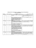
Transcription of API Standard 521 - Guide for Pressure-Relieving …
1 StandaEditionSectionInquiry #QuestionReply521 4th - March : The paragraph Check valve Malfunction says "..In these cases, one should consider providing a secondary device to minimize the potential for reversal of flow..". Should I understand the meaning "minimize" as "avoid" ?Experience has shown that a single check valve is not an effective means for preventing overpressure by reverse flow from a high- pressure source. Experience has also shown that when properly inspected and maintained series check valves are sufficient to eliminate significant reverse flow. However, some check valve seat leakage may still occur. The user needs to determine if this leakage is significant to warrant additional protection measure such as isolation 4th - March relief valves sized in accordance with Table 2 need to be sized for full flow?Table 2 provides a general listing of possible overpressure scenarios and the basis for determining relief loads.
2 Ultimately, the user needs to define which overpressure scenario from Table 2 is applicable to specific equipment, as well as the flow rate for sizing the relief 4th - March indicates that portions higher than 25 ft are normally excluded from effect of fire on the wetted surface of a vessel. On the other hand, in , on the effect of fire on the unwetted surface of a vessel, height limitation is not mentioned. However, with the same concept as the wetted surface area, I understand that if a vessel containing vapor is elevated higher than 25 ft above the source of flame, the effect of fire on the unwetted surface of the vessel is not necessarily considered. Could you please advise whether my understanding is correct or not?Neither the wetted or the unwetted surfaces of equipment higher than 25 ft ( m) above the surface of the pool fire is normally included when determining relief load.
3 An exception would be spheres (see Table 4 in the 4th Edition of API RP 521) where, at a minimum, the entire bottom hemisphere is 4th - March the heat load from the fire be considered when designing a vapor depressuring system for a dense phase heat input from the fire is generally ignored when designing vapor depressuring systems for vessels containing gases or dense phase fluids ( , fluids above the thermodynamic critical pressure ). The user may choose to consider the additional contribution of fire heat load during depressuring by, for example, the use of Equation 4th - March Table 5521-I-08/03 Background: Does Table 5 apply to atmospheric solvent storage tanks in the case of fire engulfment?No, API RP-521 scope is pressurized equipment (design pressure of > 15 psig ( barg)). Atmospheric storage tanks are covered in API Standard 2000, 5th Edition, April 1998.
4 Table 4A and 4B provide environment factors for insulation as well as grading ( , impoundment away from the tank).521 4th - March : I am trying to estimate the relieving load from a vessel exposed to external fire. This particular vessel is liquid filled and the relieving conditions are in the supercritical region (that is, the pressure relieve valve has a set pressure above the fluid's critical pressure ).Question 1: Section states that the rate of vapor discharge depends only on the rate at which the fluid will expand as a result of the heat input. Could you please clarify the meaning of this statement?Question 2: Is it still valid to use a latent heat of vaporization of 50 BTU/hr for purposes of estimating the vapor load?Reply 1: When pressure relieving conditions are above the critical point, the rate of vapor discharge depends only on the rate at which the fluid will expand as a result of the heat input because a phase change does not 2: The appropriate application of various assumptions and methodologies regarding transient behavior of the system , and selection of device sizing calculations is left to the user s 4th - March : Where does API 521 recommend sizing the pressure safety valve for two-phase relief in a fire case?
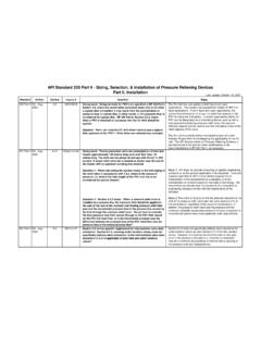
5 Experience has shown that for typical processes, two-phase relief device sizing is not normally required for the fire case provided that the relief device is located in the vapor space or on the top of the vessel. Two-phase relief device sizing should be considered for fire cases involving unusually foamy materials or reactive Standard 521 - Guide for Pressure-Relieving and Depressuring Systems Last update: October 23, 2012 StandaEditionSectionInquiry #QuestionReplyAPI Standard 521 - Guide for Pressure-Relieving and Depressuring Systems Last update: October 23, 2012521 4th - March 521-I-05/02 Background: The argument for applying the two-thirds rule in API 521 is that the equipment hydrostatic test pressure is 150 percent of the design pressure . ASME VIII Div. 1 section UG-99 edition 1998 with 1999 addenda have now changed the required hydrostatic test pressure from the 150 percent to 130 percent.
6 We therefore assume that the 150 percent in section of API 521 now must be read as 130 percent, meaning that pressure relief for tube rupture now must be provided when the design pressure of the low pressure system multiplied with is lesser than the design pressure of the high pressure system . Please inform if this assumption is correct. Can the "old" two- thirds rule still be applied If we continue to test the low pressure side (and low pressure system ) with a hydrostatic pressure of time the design pressure ?API RP-521, 4th Edition, March 1997, paragraph indicates that complete tube failure is not a viable contingency when the design pressure of the low pressure side is equal to or greater than two-thirds of the design pressure of the high pressure side. In general, failure of the low pressure side would not be expected provided a tube failure does not cause the low pressure side to exceed it s hydrostatic test pressure .
7 The two-thirds rule assumes the low pressure side test pressure was 150 percent of the design pressure . A more general guidance would be to consider a tube failure if the test pressure of the low pressure system (heat exchanger and piping) can be 4th - March : My company is working on the construction of a gas plant. There is an existing finger-type slug catcher in the inlet section of this plant that receives a three-phase gas stream from a 30-inch pipeline. This slug catcher has been designed based on ASME but its design pressure is different with the incoming pipeline. I have the following question regarding of depressurization system for this part of the plant. Question: Is there any requirement to depressurize this system in case of fire detection? If yes, please let me know if the criteria are based on API 521, Section 3 19 or are there other criteria for this case?
8 API 521 does not provide depressurization guidance for specific types of equipment or vessels. It is up to the user to define what equipment is 4th - March : The wording in Section appears to make a differentiation between a fire depressuring scenario and a process upset depressuring scenario. This wording is repeated in the second paragraph with respect to depressuring thick-wall vessels to 50%. In the fifth paragraph, however, it appears that when a fire is controlling, API recommends the depressuring of all vessels (including thick wall vessels) to 100 gauge (690 kPa) of 50% of the vessel design pressure , whichever is lower, in 15 : Does emergency depressuring only apply to systems greater than 250 (1724 kPa) with a vessel wall thickness greater than 1 in. (25 mm), or can it be used to depressure any system ?Reply: Equipment operating below 250 (1724 kPa) may not necessarily need emergency depressuring since the consequences of equipment failure due to fire exposure would be less than that for larger high- pressure statement where fire is controlling is intended to separate those applications where there are no reactive hazards.
9 If there is a reactive hazard that can cause loss of containment due to over-temperature, then emergency depressuring valves may be appropriate for equipment designed for any range of pressures or services. For equipment below 250 (1724 kPa) in light hydrocarbon service, emergency depressuring may be provided. One of the original intents was to provide emergency depressuring LPG vessels to prevent BLEVE during fire exposure. Generally, systems in LPG service will have a design pressure of 250 (1724 kPa) or less. Consequently, the plate thickness is often less than one inch. As stated in , a greater depressuring rate may be required for vessels with wall thicknesses less than one inch. This implies that depressuring to 100 psig is not a requirement for the higher pressure #QuestionReplyAPI Standard 521 - Guide for Pressure-Relieving and Depressuring Systems Last update: October 23, 2012521 4th - March : The wording in Section appears to make a differentiation between a fire depressuring scenario and a process upset depressuring scenario.
10 This wording is repeated in the second paragraph with respect to depressuring thick-wall vessels to 50%. In the fifth paragraph, however, it appears that when a fire is controlling, API recommends the depressuring of all vessels (including thick wall vessels) to 100 gauge (690 kPa) of 50% of the vessel design pressure , whichever is lower, in 15 : Does emergency depressuring only apply to systems greater than 250 (1724 kPa) with a vessel wall thickness greater than 1 in. (25 mm), or can it be used to depressure any system ?Equipment operating below 250 (1724 kPa) may not necessarily need emergency depressuring since the consequences of equipment failure due to fire exposure would be less than that for larger high- pressure statement where fire is controlling is intended to separate those applications where there are no reactive hazards.