Transcription of Application Note AN-1068 revA Considerations for …
1 Application Note AN-1068 revA Considerations for Designs using radiation - hardened solid State Relays By Alan Tasker Table of Contents Introduction Page Overview .. 1 The Contact .. 1 Actuation .. 1 The IR Advantage 1. Input Buffer ..3 2. Normally Closed Contacts ..4 The Product Application Hints General SSR Switching Times ..8 Single Shot High Current Pulse Generator ..12 Sequencing High Current Pulse design for Survivability in a radiation radiation Simulation Model ..16 Manufacturers of satellites, satellite launch vehicles, and tactical weapon systems face many challenges when designing electro-mechanical relays (EMR) into their systems. Some method of cushioning must be employed in order to prevent false relay operation when encountering shock and vibration. In addition, hash filters are sometimes necessary to debounce the contacts, thus adding space and weight.
2 However, solid State Relays (SSR) are immune to the shock and vibration levels normally encountered, and do not need contact filters. Hence, the use of solid State Relays in place of the mechanical type leads to a more reliable end product. AN-1068 revAInternational Rectifier 233 Kansas Street, El Segundo, CA 90245 USAz Considerations for Designs UsingRadiation- hardened solid State RelaysBy Alan Tasker,SSR Product Line Manager, IR Hi-Rel Products GroupIntroductionManufacturers of satellites, satellite launch vehicles, and tactical weapon systems face many chal-lenges when designing electro-mechanical relays (EMR) into their systems. Some method of cush-ioning must be employed in order to prevent false relay operation when encountering shock andvibration. In addition, hash filters are sometimes necessary to debounce the contacts, thus addingspace and weight. However, solid State Relays (SSR) are immune to the shock and vibration levelsnormally encountered, and do not need contact filters.
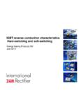
3 Hence, the use of solid State Relays in placeof the mechanical type leads to a more reliable end an SSR, various electronic elements are used to take the place of the electro-mechanical ele-ments in a mechanical relay. These are described as Contact An SSR uses a MOSFET in place of the mechanical contact. This is why there is no contact , if there is any significant power dissipation involved, then proper heat sinking will benecessary. Actuation The traditional relay uses an electromagnet in conjunction with other mechanical components toeffect contact actuation. The SSR employs a photovoltaic isolator (PVI). As a minimum, a PVIconsists of one or more LEDs and a photovoltaic array. When a current is run through the LED(s),the light output falls on the array, generating a voltage that charges the FET gate. This turns theSSR on. There must also be a gate discharge circuit present to insure that the MOSFET turns off of the physical separation between the LED(s) and the array, there is at least 1000 Volts ofisolation between the input and the output of an order to handle AC, a second MOSFET is added, as shown in figure SPST NO (Form A) AC SSR Circuit SchematicFigure SPST NO (Form A) DC SSR Circuit Schematica controlled manner when it is desired to turn the SSR off.
4 An SSR constructed as described isshown in Figure 1. In relay terms, this particular configuration is called a Single Pole, Single Throw,Normally Open (SPST NO) type. It is also called a Form A relay. Since the MOSFET has a bodydiode, this arrangement does not block current flow in both directions, so it is used only in IR Advantage1. Input Buffer The coil in most mechanical relays has sufficient resistance such that it does not need an inputbuffer. Coils are usually constructed so that actuation occurs at reasonable currents when con-nected to its rated Voltage, such as 5, 12, 15, or 24 Volts. The LED in the SSR, however, is a lowimpedance device, so some method of current limiting must be employed. This can be built in,along with a logic level activated input buffer, as shown in Figure 3. This buffer, unlike a bipolartransistor buffer, draws no current from the logic driver, greatly simplifying the One type of SSR Input Normally Closed Contacts Most MOSFETs are constructed by a process that leads to a normally off state, also called anenhancement mode device.
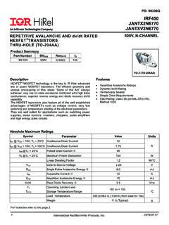
5 The Application of a gate voltage enhances the drain-to-source chan-nel, turning the device on and allowing the channel to conduct current. This mode fulfills what iscalled a Normally Open (NO) or a Form A contact in an , normally on FETs are rare. IR, however, has a set of processes that enable us to makethis type of FET as well, and these are called depletion mode devices. These fulfill the role of whatis called a Normally Closed (NC) or a Form B contact. In addition, by packaging one of each type ofcontact in a single package, a Single Pole, Double Throw (SPDT) SSR can be made. This is alsocalled a Form C RDHA718SD10C1BK Single Pole, Double Throw (Form C) DC the actuation voltage for each FET type is of the opposite polarity, two opto-couplers must beused. This leads to additional flexibility because the two sides (NO and NC) are independent andare not tied together as they would be in an EMR.
6 Additional circuitry may be built in to accomplishBreak-Before-Make (BBM), or Make-Before-Break (MBB) operation when the two inputs are drivensimultaneously, another IR Product LineAt the time of this writing, the A Series product line consists of the following Number Current Rating Package Voltage Contacts Channels per pkg Input Buffer RDHA718SE10A2QK 18 SMT 100 V SPST NO (Form A) 2 5V, controlled RDHA718FE10A2QK Flange RDHA718SE10A2SK SMT , controlled RDHA718FE10A2SK Flange RDHA718SE13A2SK SMT 130 V RDHA718FE13A2SK Flange RDHA718SE10A2FK SMT 100 V V.
7 Fast RDHA718FE10A2FK Flange RDHA718SE13A2FK SMT 130 V RDHA718FE13A2FK Flange RDHA720SF06A1NK 20 SMT 60 V SPST NO (Form A) 1 No Buffer RDHA720FF06A1NK Flange RDHA703NM10A1NK 3 SMD4 100 SPST NO (Form A) 1 No Buffer RDHA701FP10A8CK A Flat Pack 100 SPST NO (Form A) 8 No Buffer RDHA701FP10A8QK 5 V, controlled in development are the following SPDT (Form C) Number Current Rating Package Voltage Contacts Channels per pkg Input Buffer RDHA718SD10C1BK 18 SMT 100 SPDT (Form C)
8 1 V RDHA718FD10C1BK Flange RDHA718SD13C1BK SMT 130 RDHA718FD13C1BK Flange For iterations on any of the above, or for something completely different, please contact your IRrepresentative, your IR area Sales Manager, or the Leominster HintsGeneral UseBecause of the inherent isolation in the SSR, it can be used to drive either the high side or the lowside, or even between sides, as in a solar array battery charger. Figures 5 through 7 show sometypical applications:Figure One of Eight Channels in an RDHA701FP10A8QK Driving a Heater Element on the high An RDHA703NM10A1K Driving a Lamp on the Low SideFigure An RDHA718SE10A2QK Being Used to Control Battery ChargingIn Figure 7, an isolation diode must be used to prevent battery discharge into the solar array throughthe FET body diode when off, not charging.
9 Another way to accomplish the same thing with lesspower dissipation is to use an AC SSR (or to use both channels of a dual DC SSR connected inseries, source to source) in place of the DC SSR/diode combination shown Switching TimesEMRs do not switch very fast, perhaps in the neighborhood of 5-20 milliseconds. The switching timeof a normally constructed SSR is in the same ballpark, due primarily to the poor current transferratio of the PVI. (The PVI output current has to charge the gate capacitance of the output FET, andthis takes time.) For most applications, this medium speed response is other applications, system designers may be concerned with dV/dt and/or dI/dt. Keeping thesevalues low helps keep system interference at acceptable levels. Some SSRs are constructed withadditional internal circuitry that keep dV/dt and dI/dt at controlled levels, thus helping to reducesystem RFI and EMI. One consequence of this controlled ( slow) switching is that the MOSFET transitions its active region slowly.
10 If turn-on transients are expected ( due to a capacitive load,for instance), an analysis must be performed to ensure that the design does not violate the MOSFETSafe Operating Area (SOA) limits. One method of limiting the current surge is to provide a smallresistor in series with the load. Figure 8 shows one way of accomplishing this. The 1-Ohm resistorlimits surges to 28 Amps peak, well within the capabilities of an 18 Amp rated Surge Current Limiting using a 1-Ohm proper circuit operation does not permit leaving the current limiting resistor in the circuit perma-nently, it can be bypassed by a second SSR. The second SSR turns on slightly delayed from themain load SSR. This is shown in Figure Sequenced Switching Out of a Current Limiting SSRs have a multi-purpose input circuit. These can be configured for automatic bypassing ofthe current limiting resistor. This is shown in Figure 10. The current limiting resistor for the second(bypass) SSR sets the input LED current in the 10-20 mA Automatic bypassing of a current limiting yet other applications, a faster turn-on is either desired, or required because of the presence ofturn-on transients.