Transcription of Axial piston pumps PVPC - atos.com
1 Table A160-13/E. Axial piston pumps type PVPC. variable displacement, by a full line of mechanical controls PVPC are variable displacement Axial piston pumps for high pressure opera- tion, with low noise level, suitable for hydraulic oils or synthetic fluids having symilar lubricating characteristics. The actual displacement is dependent on the lenght of stroke of the pumping pistons . This lenght of stroke is determined by the position of the swa- shing plate that is achieved by two servo pistons with differential areas, against a spring . The rotating barrel forces the pistons in a circular path in and out of the bar- rel and fluid displacement takes place. Typical section on side shows version L with manual pressure compensator and flow regulation . The available hydraulic controls are shown in sections 8. The wide range of electrohydraulic proportional controls is shown in tab.
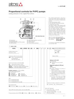
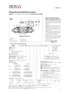
2 A170. SAE J744 mounting flange and shaft (see note 1). Max displacement: 29-46-73-88 cm3/rev. PVPC-L-4046 Max pressure: 280 bar working 350 bar peak. 1 MODEL CODE. PVPC X2E C 4 046 / 31044 / 1 D X 24DC 10 /*. Variable displacement Seals material: Axial piston pump omit for NBR (mineral oil & water glycol). Series PE = FPM. number See notes in section 2. Additional suffix for pumps with through shaft: XA = intermediate flange SAE A Supply voltage, see section 5. XB = intermediate flange SAE B (only for CH version). XC = intermediate flange SAE C (only for size 5). X = without connector (only for CH version). Additional suffix for double pumps : See section 4 for available connectors, to be ordered separately X2E = with a fixed displacement pump type PFE (see tab. A005). Direction of rotation (viewed at the shaft end). D = clockwise Type of control (see section 8): S = counterclockwise C = manual pressure compensator CH = manual pressure compensator, with venting Shaft (SAE Standard) (2): R = remote pressure compensator 1 = keyed (7/8 for 029 - 1 for 046 - 1 1/4 for 073 and 090).
3 L = load sensing (pressure & flow) 5 = splined (13 teeth for 029 - 15 for 046 - 14 for 073 and 090). LW= constant power (combined pressure & flow). For electrohydraulic proportional controls, see Type of PFE (for double pumps ), see tab. A005. table A170. Max displacement of Axial piston pump (1): Size: 029 = 29 cm3/rev 3 = for displacement 029 046 = 46 cm3/rev 4 = for displacement 046 073 = 73 cm3/rev 5 = for displacement 073 and 090 090 = 88 cm3/rev 1) optional intermediate displacements 35 and 53 cc/rev are available on request 2) pumps with ISO 3019/2 mounting flange and shaft (option /M) are available on request 2 OPERATING CHARACTERISTICS. Pump model PVPC-*-3029 PVPC-*-4046 PVPC-*-5073 PVPC-*-5090 External load position Displacement [cm3/rev] 29 46 73 88. Theoretical max flow at 1450 rpm [l/min] 42 66,7 105,8 127,6. Max working pressure / Peak pressure [bar] 280/350 280/350 280/350 250/315.
4 Min/Max inlet pressure [bar abs.] 0,8 / 25 0,8 / 25 0,8 / 25 0,8 / 25. Max pressure on drain port [bar abs.] 1,5 1,5 1,5 1,5. Power consumption at 1450 rpm and at [kW] Fax = Axial load 19,9 31,6 50,1 54,1. maximum pressure and displacement Frad = radial load Type 1 Type 5 Type 1 Type 5 Type 1 Type 5 Type 1 Type 5. Max torque on the first shaft [Nm] Notes: For speeds over 1800 rpm the inlet port must be 210 270 350 440 670 810 670 810 under oil level with adequate pipes. Max permissible load Fax 1000 1500 2000 2000 Maximum pressure for all models with water glycol fluid [N]. on drive shaft Frad 1500 1500 3000 3000 is 160 bar, with option /PE is 190 bar. Max speed with options /PE and for water glycol fluid is Speed rating [rpm] 500 3000 500 2600 500 2600 500 2200. 2000/1900/1600/1500 rpm respectively for the four sizes. A160. 3 MAIN CHARACTERISTICS OF VARIABLE DISPLACEMENT Axial piston PUMP TYPE PVPC.
5 Installation position Any position. The drain port must be on the top of the pump. Drain line must be separated and unrestricted to the reservoir and extended below the oil level as far from the inlet as possible. Suggested maximum line lenght is 3 m. Ambient temperature from -20 C to +70 C. Fluid Hydraulic oil as per DIN ; for other fluids see section 1. Recommended viscosity 15 100 mm2/sec at 40 C (ISO VG 15 100). Maximum start-up viscosity: 1000 mm2/sec Fluid contamination class ISO 4401 class 21/19/16 NAS 1638 class 10 (filters at 25 m value with 25 75 recommended). Fluid temperature -20 C +60 C -20 C +50 C (water glycol) -20 C +80 C (seals /PE). Coils characteristics (for version CH). Insulation class H. Connector protection degree IP 65. Relative duty factor 100%. Supply voltage and frequency See electric feature 5. Supply voltage tolerance 10%.
6 4 ELECTRIC CONNECTORS ACCORDING TO DIN 43650 FOR VERSION CH. The connectors must be ordered separately Code of connector Function SP-666 Connector IP-65, suitable for direct connection to electric supply source SP-667 As SP-666 connector IP-65 but with built-in signal led, suitable for direct connection to electric supply source 5 ELECTRIC FEATURES FOR VERSION CH. External supply Power Nominal Coil nominal voltage 10% consumption courrent characteristics DIRECT 12 DC 1,61 A. 19,2 W Insulation Class: CURRENT 24 DC 0,80 A. H. Protection degree: 24/50AC 0,89 A IP65. ALTERNATE. 110/50 AC 19 W 0,19 A. CURRENT. 220/50 AC 0,09 A. Average values based ambient/coil temperature of 20 C. 6 INSTALLATION POSITION. VERTICAL INSTALLATION. D2. D2 D2. D2. B. B. A. IN IN. C. C. IN. D1. The pump is supplyed whit drain D2 open, INSIDE THE TANK INSIDE THE TANK OUTSIDE THE TANK, above oil level and D1 plugged.
7 Before installation fill the Minimum oil level equal or above the pump Minimum oil level below the pump moun- Minimum inlet pressure = 0,8 bar absolute pump with hydraulic oil for at least 3/4 of its mounting surface. ting surface. B 800mm, C= 200mm volume, keeping it in horizontal position. A 200mm Minimum inlet pressure = 0,8 bar absolute With exception of pump mounted below the B 800mm, C= 200mm oil level, we recomend to interpose a baffle plate between inlet and drain line. HORIZONTAL INSTALLATION. D2. D2 IN. C. D2. D2. B. B. C. IN. C. IN IN. A. INSIDE THE TANK INSIDE THE TANK OUTSIDE THE TANK, above oil level OUTSIDE THE TANK, below oil level Minimum oil level equal or above the pump Minimum oil level below the pump moun- Minimum inlet pressure = 0,8 bar (absolute) C= 200mm mounting surface. ting surface. B 800mm, C= 200mm A 200mm Minimum inlet pressure = 0,8 bar (absolute).
8 B 800mm, C= 200mm IN: inlet line - D1: drain line - A: minimum distance between inlet and drain line - B+C: permissible suction height - C: inlet line immersion dept 7 DIAGRAMS at 1450 rpm (based on mineral oil ISO VG 46 at 50 C). Noise level curves Ambient noise levels measured in compliance with ISO 4412-1 oleohydraulics -Test procedure to define the ambient noise level - pumps Shaft speed: 1450 rpm. = Qmax = Qmin PVPC-*-3029 PVPC-*-4046 PVPC-*-5073 and PVPC-*-5090. Noise level [dB]. Noise level [dB]. Noise level [dB]. Operating pressure [bar] Operating pressure [bar] Operating pressure [bar]. Operating limits 1 = Volumetric efficiency 4 = Power consumption with full flow 2 = Overall efficiency 5 = Power consumption at pressure compensation 3 = Flow versus pressure curve PVPC-*-3029 PVPC-*-4046 PVPC-*-5073. 1 1 1. Efficiency [%]. Efficiency [%].
9 Efficiency [%]. 2 2. 2. Power consumption [kW]. Power consumption [kW]. Power consumption [kW]. 3 3. 3. 4. Flow [l/min]. Flow [l/min]. Flow [l/min]. 4 4. 5 5 5. Operating pressure [bar] Operating pressure [bar] Operating pressure [bar]. Response times PVPC-*-5090. Response times and pressure peack 1. Pressure [bar]. Efficiency [%]. due to variation 0% 100% 0% of 2. the pump displacement, obtained with Power consumption [kW]. an istantaneously opening and shut-off of the delivery line. 3. Pump type T1 (ms) T2 (ms). max Swashing plate angle 4. Flow [l/min]. PVPC-*-3029 31 19. PVPC-*-4046 44 20. 5. PVPC-*-5073 50 25. min PVPC-*-5090 53 28 Operating pressure [bar]. Time [ms]. Variation of inlet pressure and reduc- tion of displacement with increasing speed rating Speed rating [rpm/rpmmax]. Inlet pressure [rbar abs.]. Displacement rating [cm3/cm3max].
10 A160. 8 HYDRAULIC AND ELECTROHYDRAULIC CONTROLS. Hysteresis and pressure increasing; max 4 bar C Manual pressure compensator The pump displacement decreases when the line pressure approaches the setting pressu- re of the compensator. The pump supplies Flow [l/min]. only the fluid required by the system. Pressure may be steplessly adjusted at the pilot valve. Compensator setting range: 20 350 bar (315 bar for 090). Compensator standard setting: 280 bar (250 bar for 090) Pressure [bar]. Hysteresis and pressure CH Manual pressure compensator increasing; max 4 bar with venting As C plus venting function, when a long unloading time is required and heat genera- tion and noise have to be kept at lowest Flow [l/min]. level. Venting valve solenoid voltage, see section 5. Venting valve OFF = null displacement Venting valve ON = max displacement Compensator setting range: 20 350 bar (315 bar for 090) Pressure [bar].