Transcription of B120/B - B160/B - Diodes Incorporated
1 Green B120/B - B160/B . SURFACE MOUNT SCHOTTKY BARRIER RECTIFIER. Product Summary Features and Benefits B120/B , B130/B, B140/B Guard Ring Die Construction for Transient Protection VF max (V) TA = IR max (mA) TA Ideally Suited for Automated Assembly VRRM (V) IO (A). +25 C = +25 C Low Power Loss, High Efficiency 20/30/40 Surge Overload Rating to 30A Peak For Use in Low Voltage, High Frequency Inverters, Free B150/B, B160/B . Wheeling, and Polarity Protection Application VF max (V) TA = IR max (mA) TA. VRRM (V) IO (A). +25 C = +25 C Lead-Free Finish; RoHS Compliant (Notes 1 & 2). 50/60 Halogen and Antimony Free.
2 Green Device (Notes 3). Description and Applications Mechanical Data This Schottky Barrier Rectifier is designed to meet the general Case: SMA/SMB. requirements of commercial applications. It is ideally suited for use Case Material: Molded Plastic. as: UL Flammability Classification Rating 94V-0. Moisture Sensitivity: Level 1 per J-STD-020. Polarity Protection Diode Terminals: Lead Free Plating (Matte Tin Finish). Re-Circulating Diode Solderable per MIL-STD-202, Method 208. Switching Diode Polarity: Cathode Band or Cathode Notch Weight: SMA grams (Approximate). SMB grams (Approximate).
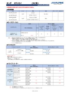
3 Top View Bottom View Ordering Information (Note 4). Part Number Qualification Case Packaging B1XX-13-F Commercial SMA 5,000/Tape & Reel B1 XXB-13-F Commercial SMB 3,000/Tape & Reel *xx = Device Type, B120-13-F (SMA Package); B120B-13-F (SMB Package). Notes: 1. EU Directive 2002/95/EC (RoHS) & 2011/65/EU (RoHS 2) compliant. All applicable RoHS exemptions applied. 2. See for more information about Diodes Incorporated 's definitions of Halogen- and Antimony-free, "Green". and Lead-free. 3. Halogen- and Antimony-free "Green products are defined as those which contain <900ppm bromine, <900ppm chlorine (<1500ppm total Br + Cl) and <1000ppm antimony compounds.
4 4. For packaging details, go to our website at Marking Information B1X0 = Product Type Marking Code, ex: B120 (SMA package). B1X0B = Product Type Marking Code, ex: B160B (SMB package). = Manufacturers' Code Marking YWW = Date Code Marking Y = Last Digit of Year (ex: 15 for 2015). WW = Week Code (01 to 53). B120/B - B160/B 1 of 5 October 2016. Document number: DS13002 Rev. 19 - 2 Diodes Incorporated B120/B - B160/B . Maximum Ratings (@TA = +25 C, unless otherwise specified.). Single phase, half wave, 60Hz, resistive or inductive load For capacitance load, derate current by 20%. Characteristic Symbol B120/B B130/B B140/B B150/B B160/B Unit Peak Repetitive Reverse Voltage VRRM.
5 Working Peak Reverse Voltage VRWM 20 30 40 50 60 V. DC Blocking Voltage VR. RMS Reverse Voltage VR(RMS) 14 21 28 35 42 V. Average Rectified Output Current @ TT = +130 C IO A. Non-Repetitive Peak Forward Surge Current IFSM 30 A. Single Half Sine-Wave Superimposed on Rated Load Thermal Characteristics Characteristic Symbol B120/B B130/B B140/B B150/B B160/B Unit Typical Thermal Resistance Junction to Terminal (Note 5) R JT 20 C/W. Operating and Storage Temperature Range TJ, TSTG -65 to +150 C. Electrical Characteristics (@TA = +25 C, unless otherwise specified.). Characteristic Symbol Min Typ Max Unit Test Condition B120/B , B130/B, B140/B - - IF = Forward Voltage Drop VF V.
6 B150/B, B160/B - - IF = - - @ Rated VR, TA = +25 C. Leakage Current (Note 6) IR mA. - - 10 @ Rated VR, TA = +100 C. Total Capacitance CT - - 110 pF VR = 4V, f = 1 MHz 2. Notes: 5. Thermal Resistance: Junction to terminal, unit mounted on PC board with mm ( mm thick) copper pads as heat sink. 6. Short duration pulse test used to minimize self-heating effect. 10 10. IF , INSTANTANEOUS FORWARD CURRENT (A). IF , INSTANTANEOUS FORWARD CURRENT (A). T A = 150 C. T A = 150 C. T A = 125 C. T A = 125 C. 1 1. TA = 25 C. T A = 100 C T A = 75 C. T A = 85 C. T A = -25 C. T A = 25 C T A = -55 C.
7 0 1 0 VF , INSTANTANEOUS FORWARD VOLTAGE (V). V F, INSTANTANEOUS FORWARD VOLTAGE (V) Figure 2 Typical Forward Characteristics Figure 1 Typical Forward Characteristics B150/B through B160/B . B120/B - B160/B 2 of 5 October 2016. Document number: DS13002 Rev. 19 - 2 Diodes Incorporated B120/B - B160/B . 10000 10000. IR, INSTANTANEOUS REVERSE CURRENT ( A). IR, INSTANTANEOUS REVERSE CURRENT ( A). T A = 150 C. T A = 150 C. 1000. 1000. T A = 125 C. TA = 125 C. T A = 100 C 100. 100. T A = 85 C. TA = 75 C. 10. 10. 1. T A = 25 C. 1. T A = 25 C. 0 10 20 30 40 50 0 10 20 30 40 50 60. VR , INSTANTANEOUS REVERSE VOLTAGE (V).
8 VR, INSTANTANEOUS REVERSE VOLTAGE (V). Figure 3 Typical Reverse Characteristics B120/B through B140/B Figure 4 Typical Reverse Characteristics B150/B through B160/B . 1,000. IO, AVERAGE RECTIFIED CURRENT (A). CT, TOTAL CAPACITANCE (pF). 100. 10 0. 1 10 100 25 50 75 100 125 150. VR, DC REVERSE VOLTAGE (V) TT, TERMINAL TEMPERATURE ( C). Fig. 5 Total Capacitance vs. Reverse Voltage Fig. 6 Forward Current Derating Curve 40. IFSM, PEAK FORWARD SURGE CURRENT (A). Single Half Sine-Wave 30. 20. 10. 0. 1 10 100. NUMBER OF CYCLES AT 60 Hz Fig. 7 Max Non-Repetitive Peak Forward Surge Current B120/B - B160/B 3 of 5 October 2016.
9 Document number: DS13002 Rev. 19 - 2 Diodes Incorporated B120/B - B160/B . Package Outline Dimensions Please see for the latest version. B. SMA SMB. Dim Min Max Dim Min Max A C A A B B C C D D D E E G G H H J J J All Dimensions in mm All Dimensions in mm H G. E. Suggested Pad Layout Please see for the latest version. X1 SMA SMB. Dimensions X (in mm) (in mm). C G Y X X1 Y G. C. B120/B - B160/B 4 of 5 October 2016. Document number: DS13002 Rev. 19 - 2 Diodes Incorporated B120/B - B160/B . IMPORTANT NOTICE. Diodes Incorporated MAKES NO WARRANTY OF ANY KIND, EXPRESS OR IMPLIED, WITH REGARDS TO THIS DOCUMENT, INCLUDING, BUT NOT LIMITED TO, THE IMPLIED WARRANTIES OF MERCHANTABILITY AND FITNESS FOR A PARTICULAR PURPOSE.
10 (AND THEIR EQUIVALENTS UNDER THE LAWS OF ANY JURISDICTION). Diodes Incorporated and its subsidiaries reserve the right to make modifications, enhancements, improvements, corrections or other changes without further notice to this document and any product described herein. Diodes Incorporated does not assume any liability arising out of the application or use of this document or any product described herein; neither does Diodes Incorporated convey any license under its patent or trademark rights, nor the rights of others. Any Customer or user of this document or products described herein in such applications shall assume all risks of such use and will agree to hold Diodes Incorporated and all the companies whose products are represented on Diodes Incorporated website, harmless against all damages.