Transcription of Backfill Material Selection
1 INSTALLATION GUIDE. Storm Water Quality Units IG October 2008. ADS polyethylene products and a well-constructed Backfill envelope work together to support soil and live loads. Although Backfill has special significance in applications involving high loads, it is important to take reasonable precautions during any pipe installation. Correct installation will ensure long-term trouble-free service for all types of pipe systems. The recommendations presented here detail how to correctly install Water Quality Units. Installation with proper Backfill materials, compaction levels, and placement procedures are essential to achieve long term system performance. These recommendations assume the drainage designer used design criteria available from ASTM.
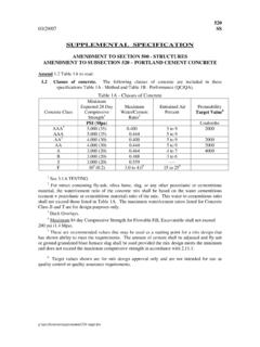
2 D2321 and ADS. The designer should discuss installations involving conditions not covered by that document (poor soils, high loads, or other factors that may affect the performance of the system) with ADS Regional Engineers or Application Engineering through the nearest manufacturing location. All installations must comply with local, state, and federal regulations. Backfill Material Selection Structural Backfill Material must be a Class I Material described in Table 1. Native soil meeting class II, III, or IVA, as described in Table 1, are NOT acceptable initial Backfill materials. However, they may be used as final Backfill once the initial Backfill is placed and compacted. Class I materials shall be compacted to a minimum Standard Proctor Density of 95%.
3 In regions where Class I Backfill Material may not be readily obtainable, flowable fill may be a suitable alternative. Where flowable fill is used, precaution must be taken to prevent flotation during installation. Table 1. Acceptable Backfill Material and Compaction Requirements Soil Maximum*. Classification Minimum Compaction Standard Layer ASTM ASTM Density Height Description D2321 D2487 (%) (in.). flowable fill n/a n/a Dumped **. Graded or crushed stone Class I - Compacted 12 ( ). Crushed gravel Well-graded sand, gravels, GW. and gravel/sand mixtures;. Class GP Material Not Poorly graded sand,gravels II SW Recommended and gravel/sand mixtures;. SP. little or no fines Silty or clayey gravels, GM. Gravels/sand/silt or gravels Class GC Material Not and/clay mixtures, silty or III SM Recommended clayey sands, sand/clay or SC.
4 Sand/silt mixtures Inorganic silts and low to medium plasticity clays; Class ML Material Not gravelly, sandy, or silty IVA CL Recommended clays; some fine sands *Layer Heights should not exceed one-half the pipe diameter. Layer heights may also need to be reduced to accommodate compaction method. **Where flowable fill is used, precaution must be taken to prevent flotation. NOTE: These recommendations are general in nature and are not meant to be specific. Consult a geotechnical engineer for project specific design and installation recommendations. 4640 TRUEMAN BLVD. HILLIARD, OH 43026 (800) 821-6710 1. AIG201 ADS 2008. Trench Construction Trench or ditch should be just wide enough to place and compact Backfill around the entire pipe.
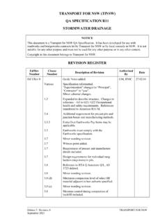
5 A minimum width of OD + 36 but no greater than ADS UNIT MINIMUM MINIMUM. OD + 72 is recommended. Trench width does not SIZE D W*. 36" ' '. account for the bypass pipe, this estimate is for (900 mm) ( M) ( M) MINIMUM UNDISTURBED. 42" ' ' EARTH. the main unit only. (1050 mm) ( M) ( M). D. 48" ' '. As with any pipe, groundwater or seasonal high (1200 mm). 60". ( M). '. ( M). '. water tables may impede installation. De-watering (1500 mm) ( M) ( M). 6" CLASS I. is necessary for safe, efficient installation. * DOES NOT ACCOUNT FOR BYPASS PIPE, Material . THIS ESTIMATE IS FOR THE MAIN UNIT ONLY. W*. Trench or ditch bottoms containing bedrock, soft muck or refuse, or other Material unable to provide long-term pipe support are unacceptable.
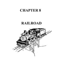
6 If a firm foundation is exposed, replace excavated Material with D. acceptable Backfill and compact as shown. Acceptable Backfill Material 2' . ( ). 3 ID. Remove rock or unyielding Material 1-foot ( ) below grade and Max ID + 4. D SOFT FOUNDATION. 6 ( ) on either side of pipe.* 12 ( ) Min Excavate soft areas approximately 2 feet ( ) below grade and .75 D Max three times pipe width.*. D + 12 ( ). If soft area remains after excavation or if native soil can migrate ROCK OR UNYIELDING Material . into Backfill , use synthetic fabric (geotextile) to separate native soil from Backfill .*. *These recommendations are general in nature and are not For a flat bottom trench, the middle of bedding equal to 1/3 the meant to be specific.
7 Consult a geotechnical engineer for project specific design and installation recommendations pipe OD shall be loosely placed while the remainder shall be compacted in accordance with Table 1. Backfill Envelope Construction Placing Unit and Initial Backfill Utilize care when lowering unit into the trench. Handle using ACCESS RISER. nylon slings and two pick points. Do not use slings around risers. ADS WATER SET ADS WQU. QUALITY UNIT ON LINE AND. INLET SIDE LEVEL. Place and compact Class I Backfill in layers to meet requirements of Table 1. CLASS I Material . Backfill TO BYPASS. OD INVERT COMPACTED. When the unit consists of two sections, place the downstream LEAVE AREA. OPEN TO. section first. Properly lube the bell and spigot to connect and SET SUMP.
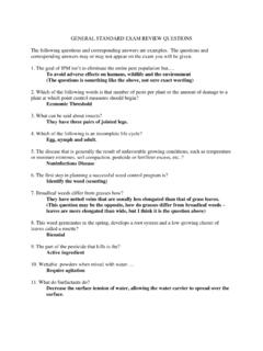
8 INLET TEE. home the remaining section. 6" BEDDING. 2 4640 TRUEMAN BLVD. HILLIARD, OH 43026 (800) 821-6710 AIG201 ADS 2008. Connecting the Bypass Start on the downstream end by connecting the outlet fitting be sure to match the inverts of the unit outlet and bypass pipe. The bypass pipe of the ADS WQU is designed to convey the peak storm water flow of the storm line. For example, at a 1% slope, peak flow rates for the bypass are as follows: Diam. (in) CFS L/S Diam. (in) CFS L/S. 12 4 100 36 72 1900. 15 7 190 42 110 2900. 18 11 300 48 160 4200. 24 24 660 60 280 7600. 30 44 1200. Bypass fittings can be connected using the same couplers as the main storm sewer pipe. Couplers may be split couplers, gasketed split couplers, bell-bell couplers or welded couplers.
9 CONNECT SEDIMENT. STORM WATER INLET TEE ACCESS. ADDITIONAL SLOPED PIPE. QUALITY UNIT FITTING RISER. EXCAVATION BY-PASS COUPLER. OUTLET SIDE. FOR BY-PASS PIPE (TYP). OUTLET. HDPE WYE. BYPASS FITTING. PIPE. COMPACTED CLASS I. Material PER ASTM. D2321 TO. BY-PASS LEVEL. MATCH INVERTS. WHEN CONNECTING. THE OUTLET FITTING. SEE TABLE FOR. MINIMUM EXCAVATION. DISTANCE. Place and compact initial Backfill in layers around pipe to at least 12 ( ) above the crown as shown. Avoid impacting pipe or separator unit with compaction equipment. Backfill Around the Unit and Bypass Distance from outside diameter of SWQU (trench side) to bypass outer trench wall are provided in the following table (see detail above for distance reference): Bypass Pipe Diameter, in (mm).
10 12 15 18 24 30 36 42 48 60. (300) (375) (450) (600) (750) (900) (1050) (1200) (1500). 41 44 49 56 64 71 78 85 100. (1041) (1118) (1245) (1422) (1626) (1803) (1981) (2159) (2540). Continue Backfill with Class I Material to 12 above the Water Quality Unit (24 for 60 units). Place and compact initial Backfill in layers around pipe to at least 12 ( ) above the crown. 4640 TRUEMAN BLVD. HILLIARD, OH 43026 (800) 821-6710 3. AIG201 ADS 2008. Avoid impacting pipe or separator unit with compaction equipment. Final Backfill and compaction should be appropriate for anticipated loading. fill unit with water to the top of the sediment weir plate once Backfill is placed and compacted 12 above the unit. Final Cover and Riser Extensions For non-traffic loading, H=12 for 36 , 42 , and 48 units measured from the top of the unit to the bottom of bituminous pavement or top of rigid pavement.