Transcription of Basic PCB material electrical and thermal properties for ...
1 Signal Processing Group Inc., technical memorandum. Website: Signal Processing Gtroup Inc., designs, develops andmanufactures analog and wireless ASICs and modules using state of the artsemiconductor, PCB and packaging technologies. For a free no obligation quote on yourproduct please send your requirements to us via email or throughthe Contact item on the PCB material electrical and thermalproperties for designIntroduction:In order to design PCBs intelligently it becomes important to understand, among otherthings, the electrical properties of the board material .
2 This brief paper is an attempt tooutline these key properties and offer some descriptions of these :The Basic ( and almost indispensable) parameters for PCB materials are listed below andfurther described in the treatment that , laminate dielectric constantdf, dissipation factorDielectric lossConductor lossThermal effectsFrequency performancedk: Use thedesign dk value which is assumed to be more pertinent to design. Determinessuch things as impedances and the physical dimensions of microstrip reasonable accurate practical formula for the effectivedielectric constant derived fromthe dielectric constant of the material is: eff= [ ( r+1)/2] +[ ( r-1)/2][1+ ( )]-1/2 Hereh = thickness of PCB materialW = width of the trace eff= effective dielectric constant r= dielectric constant of pcb materialdf: Thedissipation factor (df) is a measureof loss-rate of energy of a mode of oscillationin adissipative system.
3 It is the reciprocal of quality factor Q, which represents theSignal Processing Group Inc., technical memorandum. Website: Signal Processing Gtroup Inc., designs, develops andmanufactures analog and wireless ASICs and modules using state of the artsemiconductor, PCB and packaging technologies. For a free no obligation quote on yourproduct please send your requirements to us via email or throughthe Contact item on the of oscillation. This allowsjudgments of frequency performance of the PCBmaterial among other loss:At high frequencies, dielectric loss is dominant, and is dependent on thedissipation factor (loss tangent) for a given dielectric dielectric constant and loss factor are two of the most significant parameters thataffect the performance of PCB circuits.
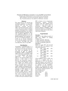
4 Dielectricloss can be explained as follows:Most capacitors, with dielectrics between the plates, lose a fraction of the energy whenan AC current is applied. In other words, the dielectric isless than perfect. The simplestmodel for a capacitor with a lossy dielectric is as a capacitor with a perfect dielectric inparallel with a resistor giving the power dissipation. The current now leads the voltage bya very little less than 90 , where thedifference (Greek letter delta) is termed thedielectric loss angle,as seen in Figure circuit for a lossy dielectricWithout bothering about the equations, the fraction of the maximum energy lost eachcycle, divided by 2 is termed the loss factor and its value is given by tan ( tan delta ).
5 Typically it is values of tan ( loss tangent) that you will find quoted in table below shows some typical values of dielectric constant, loss factor, anddielectric strength. The AC values are measured at Processing Group Inc., technical memorandum. Website: Signal Processing Gtroup Inc., designs, develops andmanufactures analog and wireless ASICs and modules using state of the artsemiconductor, PCB and packaging technologies. For a free no obligation quote on yourproduct please send your requirements to us via email or throughthe Contact item on the (breakdown) materials and substrates have their own parameters.
6 These are quoted by themanufacturer and should be dielectrics with small loss, is 1 and tan . Power decays with propagationdistancez as, where is the initial power,, is the angular frequency of the wave, and = 0 r. =permeability of the material 0 =is thepermittivity of free space. r. =is the dielectricconstant. is the wavelength in the dielectric. ( guide wavelength)Conductor loss:PCB trace conductors all cause loss of the EM wave that travels onthem. Therefore it is essential to know whether the conductors chosen will affect theperformance of the circuit at the particular power levels and frequencies.
7 The conductorloss can be described by the following iswell known that high-frequency current in a planar conductordecreasesexponentially with penetration into the conductor, falling to 1/eof its surface value at oneskin depth where = [ ]Signal Processing Group Inc., technical memorandum. Website: Signal Processing Gtroup Inc., designs, develops andmanufactures analog and wireless ASICs and modules using state of the artsemiconductor, PCB and packaging technologies. For a free no obligation quote on yourproduct please send your requirements to us via email or throughthe Contact item on the = angular frequency of signal =permeability of material = conductivity of the materialSince the thickness of the material becomes small the resistance of the conductorincreases causing loss due to skineffect addition to this the resistance and shuntconductance of the trace is a lossy system.
8 The resistance ofcourse becomes dependent onthe skin effect as well. Generally for atransmission line ( of which the PCB trace is anexample) the attenuation is given by: = { GZo + R/Zo} Np/meterHere G is the per unit length shunt conductance and Zo is the characteristic characteristic impedance is found from the relationship:Zo = [L/C]Where L and C are the transmission line constants. ( Provided by manufacturer orcalculated from the construction of the PCB).In many cases, to get a fairly close approximation , G can be neglected.
9 The resistance isofcourse also dependent on the skin depth. However, a calculation can be made withoutthe effect of skin depth and then later modified with the inclusion of skin further, if a matched condition exists between the power generator and the PCBtrace, the input power is simply,WT = 1/2[Vo2/Zo], Vo being the amplitude of the voltage average power loss along the line per unit length is:Ploss = (2WT)Knowing the amplitude of the signal expected on the trace and the other parametersdefined above conductor power loss can be assessed.
10 Of course modern simulationprograms can reduce the overload of calculations like magic, but the engineer must knowSignal Processing Group Inc., technical memorandum. Website: Signal Processing Gtroup Inc., designs, develops andmanufactures analog and wireless ASICs and modules using state of the artsemiconductor, PCB and packaging technologies. For a free no obligation quote on yourproduct please send your requirements to us via email or throughthe Contact item on the priori what toexpect, at least to an order of is for this that the expressionsabove can come in handy.