Transcription of BCD-TO-DECIMAL DECODER
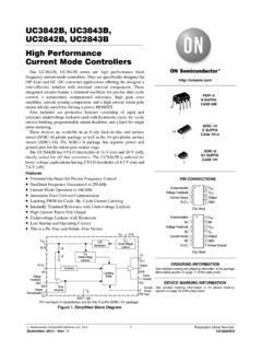
1 1/10 September 2002nBCD TO DECIMAL DECODING OR BINARY TO OCTAL DECODINGnHIGH DECODED OUTPUT DRIVE CAPABILITYn"POSITIVE LOGIC" INPUTS AND OUTPUTS:DECODED OUTPUTS GO HIGH ON SELECTIONnMEDIUM SPEED OPERATION : tPHL, tPLH = 80ns (Typ.) at VDD = 10Vn QUIESCENT CURRENT SPECIF. UP TO 20 VnSTANDARDIZED SYMMETRICAL OUTPUT CHARACTERISTICSnINPUT LEAKAGE CURRENT II = 100nA (MAX) AT VDD = 18V TA = 25 Cn100% TESTED FOR QUIESCENT CURRENT nMEETS ALL REQUIREMENTS OF jedec JESD13B "STANDARD SPECIFICATIONS FOR DESCRIPTION OF B SERIES CMOS DEVICES"DESCRIPTIONHCF4028B is a monolithic integrated circuitfabricated in Metal Oxide Semiconductortechnology available in DIP and SOP packages. HCF4028B is a BCD to DECIMAL or BINARY toOCTAL DECODER consisting of buffering on all 4inputs, decoding logic gates, and 10 BCD code applied to the four inputs, A to D,results in a high level at the selected one of 10decimal decoded outputs.
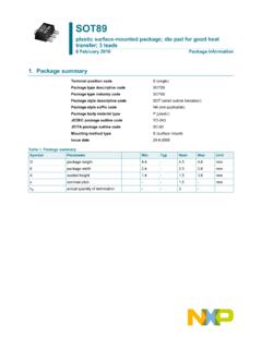
2 Similarly, a 3-bit binarycode applied to inputs A through C is decoded inoctal code at output 0 to 7 if D = "0". High drivecapability is provided at all outputs to enhance dcand dynamic performance in high TO DECIMAL DECODER PIN CONNECTIONORDER CODES PACKAGETUBET & RDIPHCF4028 BEYSOPHCF4028BM1 HCF4028M013 TRDIPSOPHCF4028B2/10 IINPUT EQUIVALENT CIRCUIT PIN DESCRIPTION FUNCTIONAL DIAGRAM TRUTH TABLE PIN NoSYMBOLNAME AND FUNCTION10, 13, 12, 11A, B, C, DBCD Data Inputs10, 13, 12A, B, C3-Bit Binary Inputs3, 14, 2, 15, 1, 6, 7, 4, 9, 5 0 to 9 Buffered DECIMAL Decoded Outputs3, 14, 2, 15, 1, 6, 7, 40 to 7 Buffered OCTAL Decoded Outputs8 VSSN egative Supply Voltage16 VDDP ositive Supply VoltageINPUTSOUTPUTSDCBA0123456789 LLLLHLLLLLLLLLLLLHLHLLLLLLLLLLHLLLHLLLLL LLLLHHLLLHLLLLLLLHLLLLLLHLLLLLLHLHLLLLLH LLLLLHHLLLLLLLHLLLLHHHLLLLLLLHLLHLLLLLLL LLLLHLHLLHLLLLLLLLLHHLHLLLLLLLLLLLHLHHLL LLLLLLLLHHLLLLLLLLLLLLHHLHLLLLLLLLLLHHHL LLLLLLLLLLHHHHLLLLLLLLLLHCF4028B3/10 LOGIC DIAGRAM ABSOLUTE MAXIMUM RATINGS Absolute Maximum Ratings are those values beyond which damage to the device may occur.
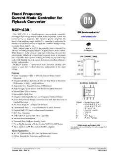
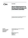
3 Functional operation under these conditions is not voltage values are referred to VSS pin OPERATING CONDITIONS SymbolParameterValueUnitVDDS upply to +22 VVIDC Input to VDD + Input Current 10mAPDP ower Dissipation per Package200mWPower Dissipation per Output Transistor100mWTopOperating Temperature-55 to +125 CTstgStorage Temperature-65 to +150 CSymbolParameterValueUnitVDDS upply Voltage3 to 20 VVII nput Voltage0 to VDDVTopOperating Temperature-55 to 125 CHCF4028B4/10DC SPECIFICATIONS The Noise Margin for both "1" and "0" level is: 1V min. with VDD=5V, 2V min. with VDD=10V, min. with VDD=15 VDYNAMIC ELECTRICAL CHARACTERISTICS (Tamb = 25 C, CL = 50pF, RL = 200K , tr = tf = 20 ns) (*) Typical temperature coefficient for all VDD value is %/ ConditionsValueUnitVI(V)VO(V) IO ( A)VDD(V)TA = 25 C-40 to 85 C -55 to 125 Current0 A0 Level Output Voltage0/5< < < Level Output Voltage5/0< < < Level Input < < <115111111 VILLow Level Input < < <115444 IOHO utput Drive Current0 Sink Current0 Leakage Current0/18any input18 10-5 1 1 ACII nput Capacitance any ConditionValue (*)UnitVDD (V) tPLHP ropagation Delay Time (Clock to "Out")5175350ns10801601560120tTHL tTLHT ransition Time(Carry Out Line)5100200ns1050100152550 HCF4028B5/10 TEST CIRCUIT CL = 50pF or equivalent (includes jig and probe capacitance)RL = 200K RT = ZOUT of pulse generator (typically 50 )WAVEFORM : PROPAGATION DELAY TIMES (f=1 MHz; 50% duty cycle) TYPICAL APPLICATION The circuit shown in fig.
4 1 converts any 4-bit codeto a decimal or hexadecimal code. Fig. 2 shows anumber of codes and the decimal or hexadecimalnumber in these codes, which must be applied tothe input pins of HCF4028B to select a particularoutput. For example: in order to get a "high" onoutput 8 the input must be either an 8 expressed in4-bit binary code or a 15 expressed 1 : CODE CONVERSION CIRCUIT FIGURE 2 : CODE CONVERSION CHART INPUTSINPUT CODESOUTPUT NUMBERHEXA DECIMALDECIMALDCBA4 BIT BINARY4 BIT GRAYEXCESS 3 EXCESS 3 GRAYAIKEN4221 0123456789101112131415 LLLL0000 HLLLLLLLLLLLLLLLLLLH1111 LHLLLLLLLLLLLLLLLLHL23022 LLHLLLLLLLLLLLLLLLHH32033 LLLHLLLLLLLLLLLLLHLL47144 LLLLHLLLLLLLLLLLLHLH5623 LLLLLHLLLLLLLLLLLHHL64314 LLLLLLHLLLLLLLLLLHHH7542 LLLLLLLHLLLLLLLLHLLL8155 LLLLLLLLHLLLLLLLHLLH91465 LLLLLLLLLHLLLLLLHLHL1012796 LLLLLLLLLLHLLLLLHLHH111385 LLLLLLLLLLLHLLLLHHLL128956 LLLLLLLLLLLLHLLLHHLH139677 LLLLLLLLLLLLLHLLHHHL1411888 LLLLLLLLLLLLLLHLHHHH1510799 LLLLLLLLLLLLLLLHHCF4028B7/10 FIGURE 3 : 6 BIT BINARY TO 1 OF 64 ADDRESS DECODER FIGURE 4.
5 NEON READOUT (NIXIE TUBE) DISPLAY APPLICATION HCF4028B8 DIP-16 ( ) MECHANICAL DATAP001 CHCF4028B9 (typ.) (max.)SO-16 MECHANICAL DATAPO13H8 HCF4028B10/10 Information furnished is believed to be accurate and reliable. However, STMicroelectronics assumes no responsibility for theconsequences of use of such information nor for any infringement of patents or other rights of third parties which may result fro mits use. No license is granted by implication or otherwise under any patent or patent rights of STMicroelectronics. Specificationsmentioned in this publication are subject to change without notice. This publication supersedes and replaces all informationpreviously supplied. STMicroelectronics products are not authorized for use as critical components in life support devices orsystems without express written approval of STMicroelectronics. The ST logo is a registered trademark of STMicroelectronics 2002 STMicroelectronics - Printed in Italy - All Rights ReservedSTMicroelectronics GROUP OF COMPANIESA ustralia - Brazil - Canada - China - Finland - France - Germany - Hong Kong - India - Israel - Italy - Japan - Malaysia - Malta - Morocco Singapore - Spain - Sweden - Switzerland - United Kingdom - United States.
6