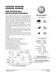
Transcription of NCP1632 - Power Factor Controller, Interleaved, 2-Phase
1 Semiconductor Components Industries, LLC, 2017 April, 2020 Rev. 71 publication Order Number: NCP1632 /DPower Factor Controller, Interleaved, 2-PhaseNCP1632 The NCP1632 integrates a dual MOSFET driver for interleavedPFC applications. Interleaving consists of paralleling two smallstages in lieu of a bigger one, more difficult to design. This approachhas several merits like the ease of implementation, the use of smallercomponents or a better distribution of the , Interleaving extends the Power range of Critical ConductionMode that is an efficient and cost effective technique (no need forlow trr diodes).
2 In addition, the NCP1632 drivers are 180 phaseshifted for a significantly reduced current in a SOIC16 package, the circuit incorporates all thefeatures necessary for building robust and compact interleaved PFCstages, with a minimum of external Features Near Unity Power Factor Substantial 180 Phase Shift in All Conditions Including TransientPhases Frequency Clamped Critical Conduction Mode (FCCrM) ,Fixed Frequency, Discontinuous Conduction Mode Operation withCritical Conduction Achievable in Most Stressful Conditions FCCrM Operation Optimizes the PFC Stage Efficiency Over theLoad Range Out of phase Control for Low EMI and a Reduced rms Current inthe Bulk Capacitor Frequency Fold back at Low Power to Further Improve the LightLoad Efficiency Accurate Zero Current Detection by Auxiliary Winding for ValleyTurn On Fast Line / Load Transient Compensation High Drive Capability: 500 mA / +800 mA Signal to Indicate that the PFC is Ready for Operation( pfcOK Pin) VCC Range.
3 From 10 V to 20 VSafety Features Output Over and Under Voltage Protection Brown Out Detection with a 500 ms Delay to Help Meet Hold upTime Specifications Soft Start for Smooth Start up Operation Programmable Adjustment of the Maximum Power Over Current Limitation Detection of Inrush CurrentsTypical Applications Computer Power Supplies LCD / Plasma Flat Panels All Off Line Appliances Requiring Power Factor CorrectionSOIC 16D SUFFIXCASE 751 BDevicePackageShipping ORDERING INFORMATIONNCP1632DR2 GSOIC 16(Pb Free)2500 / Tape & Reel For information on tape and reel specifications,including part orientation and tape sizes, pleaserefer to our Tape and Reel Packaging SpecificationBrochure, BRD8011 ASSIGNMENT(Top View)ZCD1 REF5V/pfcOKDRV1 GNDVccDRV2 LatchCSZCD2 FBRtOSCV controlFFOLDBOOVP / UVP1 MARKING DIAGRAMNCP1632 GAWLYWWA= Assembly LocationWL= Wafer LotY= YearWW= Work WeekG= Pb Free 1.
4 Typical Application SchematicEMIF ilterAc lineDRC12341316141556789121011pfcOKROCPR ZCD1 RZCD22 BULKL2L1M1M2 DCFFCCOMP2 RCOMP1 CCOMP1 RTRFOLDROUT3 ROUT1 ROVP1 ROVP3 RBO2 RBO3 CBO2 OVPinOVPinCSCFOLDROSCCOSCCINVINVOUTD bypassVOUTRBO1 ROVP2 ROUT2 VCCVAUX2 VAUX2 CpfcOKCVCCDRV1 GNDDRV2pfcOKLatchCSZCD1 ZCD2 FFOLDFBOSCV controlRtBOOVP/UVP1 Table 1. MAXIMUM RATINGSS ymbolRatingPinValueUnitVCC(MAX)Maximum Power Supply Voltage Continuous12 , +20 VVMAXM aximum Input Voltage on Low Power Pins) (Note 1)1, 2, 3, 4, 6, 7,8, 9, 10, 15,and 16 , + (MAX)VControl Pin Maximum Input Voltage5 , VControl(clamp) (Note 2)VPDRqJ APower Dissipation and Thermal CharacteristicsMaximum Power Dissipation @ TA = 70 CThermal Resistance Junction to Air550145mW C/WTJO perating Junction Temperature Range 40 to +150 CTJ(MAX)Maximum Junction Temperature150 CTS(MAX)Storage Temperature Range 65 to +150 CTL(MAX)Lead Temperature (Soldering, 10s)300 CESD Capability, HBM model (Note 3)
5 3kVESD Capability, Machine Model (Note 3)200 VESD Capability, Charged Device Model (Note 3)1000 VStresses exceeding those listed in the Maximum Ratings table may damage the device. If any of these limits are exceeded, device functionalityshould not be assumed, damage may occur and reliability may be These maximum ratings ( V / V) guarantee that the internal ESD Zener diode is not turned on. More positive and negative voltages canbe applied to the ZCD1 pin if the ESD Zener diode current is limited to 5 mA maximum. Typically, as detailed in the Zero Current Detectionsection, an external resistor is to be placed between the ZCD1 pin and its driving voltage to limit the ZCD1 source and sink currents to 5 mAor less.
6 See Figure 2 and application note AND9654 for more details. The same is valid for the ZCD2 VControl(clamp) is the pin5 clamp This device(s) contains ESD protection and exceeds the following tests:Human Body Model 2000 V per JEDEC Standard JESD22 A114 EMachine Model Method 200 V per JEDEC Standard JESD22 A115 ACharged Device Model Method 1000 V per JEDEC Standard JESD22 C101E4. This device contains latch up protection and exceeds 100 mA per JEDEC Standard pinGNDZCD1 CircuitryESDZ enerDiodeNCP1632 ZCD1 CircuitryRZCD1 IZCD1 VAUX1 Figure 2. Limit the ZCD1 pin current (IZCD1) between 5 mA and 5 mA (the same is valid for the ZCD2 pin) 2.
7 TYPICAL ELECTRICAL CHARACTERISTICS TABLE (Conditions: VCC = 15 V, Vpin7 = 2 V, Vpin10 = 0 V, TJ from 40 C, to +125 C, unless otherwise specified)CharacteristicsTest ConditionsSymbolMinTypMaxUnitSTARTUP AND SUPPLY CIRCUITSS upply VoltageStartup ThresholdMinimum Operating VoltageHysteresis VCC(on) VCC(off)Internal Logic ResetVCC increasingVCC decreasingVCC decreasingVCC(on)VCC(off)VCC(hyst)VCC(re set) currentVCC = VICC(start) 50100mASupply CurrentDevice Enabled/No output load on pin6 Current that discharges VCC in latch modeCurrent that discharges VCC in OFF modeSKIP Mode ConsumptionFsw = 130 kHz (Note 5)VCC = 15 V, Vpin10 = 5 VVCC = 15 V, pin 7 groundedVFB = 3 VICC1 ICC(latch)ICC(off)ICC(SKIP) AND FREQUENCY FOLDBACKC harge CurrentPin 6 openICH126140154mAMaximum Discharge CurrentPin 6 over ICS ratioICS = 30 mARFFOLD30 1 -Pin 6 source currentICS = 30 mAIFFOLD30283032mAOscillator Upper ThresholdVOSC(high) 5 VOscillator Lower ThresholdVFFOLD = V, VFFOLD fallingVFFOLD = V, VFFOLD fallingVFFOLD = V, VFFOLD risingVFFOLD = V, VFFOLD fallingVFFOLD = V, VFFOLD fallingVOSC(low) Swing (Note 6)
8 VFFOLD = V, VFFOLD fallingVFFOLD = V, VFFOLD fallingVFFOLD = V, VFFOLD risingVFFOLD = V, VFFOLD fallingVFFOLD = V, VFFOLD fallingVOSC(swing) SENSEC urrent Sense Voltage OffsetIpin9 = 100 mAIpin9 = 10 mAVCS(TH100)VCS(TH10) 20 10002010mVCurrent Sense Protection ThresholdTJ = 25 CTJ = 40 C to 125 CIILIM1 IILIM2202194210210226226mAThreshold for In rush Current DetectionIin rush111417mAGATE DRIVE (Note 8)Drive ResistanceDRV1 SinkDRV1 SourceDRV2 SinkDRV2 SourceIpin14 = 100 mAIpin14 = 100 mAIpin11 = 100 mAIpin11 = 100 mARSNK1 RSRC1 RSNK2 RSRC2 71571515251525 Product parametric performance is indicated in the Electrical Characteristics for the listed test conditions, unless otherwise noted.
9 Productperformance may not be indicated by the Electrical Characteristics if operated under different DRV1 and DRV2 pulsating at half this frequency, that is, 65 Not tested. Guaranteed by Not tested. Guaranteed by design and Guaranteed by design, the VCC pin can handle the double of the DRV peak source current, that is, 1 A 2. TYPICAL ELECTRICAL CHARACTERISTICS TABLE (Conditions: VCC = 15 V, Vpin7 = 2 V, Vpin10 = 0 V, TJ from 40 C, to +125 C, unless otherwise specified)CharacteristicsUnitMaxTypMinSy mbolTest ConditionsGATE DRIVE (Note 8)Drive Current Capability (Note 6)DRV1 SinkDRV1 SourceDRV2 SinkDRV2 SourceVDRV1 = 10 VVDRV1 = 0 VVDRV2 = 10 VVDRV2 = 0 VISNK1 ISRC1 ISNK2 ISRC2 800500800500 mARise TimeDRV1 DRV2 CDRV1 = 1 nF, VDRV1 = 1 to 10 VCDRV2 = 1 nF, VDRV2 = 1 to 10 Vtr1tr2 4040 nsFall TimeDRV1 DRV2 CDRV1 = 1 nF, VDRV1 = 10 to 1 VCDRV2 = 1 nF, VDRV2 = 10 to 1 Vtf1tf2 2020 nsREGULATION BLOCKF eedback Voltage Amplifier Source Current Capability@ Vpin2 = VIEA(SRC)
10 20mAError Amplifier Sink Current Capability@ Vpin2 = VIEA(SNK)+20 Error Amplifier GainGEA115200285mSPin 5 Source Current when (Vout(low)Detect) is activatedpfcOK highpfcOK lowIControl(boost)175552207026585mAPin2 Bias CurrentVpin2 = VIFB(bias) 500500nAPin 5 Voltage:@ Vpin2 = V@ Vpin2 = VVControl(clamp)VControl(MIN)VControl(ra nge) (Vout(low) Detect Threshold / VREF)(Note 6)FB fallingVout(low) (Vout(low) Detect Hysteresis / VREF)(Note 6)FB risingHout(low)/VREF MODEDuty CycleVFB = 3 VDMIN 0%RAMP CONTROL (valid for the two phases)Maximum DRV1 and DRV2 On Time(FB pin grounded)Vpin7 = V, Ipin3 = 50 mA (Note 6)Vpin7 = V, Ipin3 = 200 mAVpin7 = V, Ipin3 = 100 mAVpin7 = V, Ipin3 = 400 3 voltageVBO = Vpin7 = V, Ipin3 = 50 mAVBO = Vpin7 = V, Ipin3 = 200 mAVBO = Vpin7 = V, Ipin3 = 50 mAVBO = Vpin7 = V, Ipin3 = 200 Vton VoltageNot testedVton(MAX)