Transcription of AN1040/D Mounting Considerations For Power …
1 Semiconductor Components Industries, LLC, 2001 May, 2001 Rev. 31 Publication Order Number:AN1040/DAN1040/DMounting ConsiderationsFor Power SemiconductorsPrepared by: Bill RoehrINTRODUCTIONC urrent and Power ratings of semiconductors areinseparably linked to their thermal environment. Except forlead mounted parts used at low currents, a heat exchangeris required to prevent the junction temperature fromexceeding its rated limit, thereby running the risk of a highfailure rate. Furthermore, the semiconductor industry sfield history indicated that the failure rate of most siliconsemiconductors decreases approximately by one half for adecrease in junction temperature from 160 C to 135 C.(1)Guidelines for designers of military Power supplies imposea 110 C limit upon junction temperature.
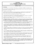
2 (2) Propermounting minimizes the temperature gradient between thesemiconductor case and the heat early life field failures of Power semiconductorscan be traced to faulty Mounting procedures. With metalpackaged devices, faulty Mounting generally causesunnecessarily high junction temperature, resulting inreduced component lifetime, although mechanical damagehas occurred on occasion from improperly Mounting to awarped surface. With the widespread use of variousplastic packaged semiconductors , the prospect ofmechanical damage is very significant. Mechanicaldamage can impair the case moisture resistance or crackthe semiconductor 1 shows an example of doing nearly everythingwrong.
3 A tab mount TO 220 package is shown being usedas a replacement for a TO 213AA (TO 66) part which wassocket mounted. To use the socket, the leads are bent anoperation which, if not properly done, can crack thepackage, break the internal bonding wires, or crack the package is fastened with a sheet metal screw througha 1/4 hole containing a fiber insulating sleeve. The forceused to tighten the screw tends to pull the package into thehole, possibly causing enough distortion to crack the die. Inaddition, the contact area is small because of the areaconsumed by the large hole and the bowing of the package;the result is a much higher junction temperature thanexpected. If a rough heatsink surface and/or burrs aroundthe hole were displayed in the illustration, most but not all,poor Mounting practices would be BODYPACKAGE HEATSINKMICA WASHERSPEED NUT(PART OF SOCKET)SHEET METAL SCREWSOCKET FORTO 213AA PACKAGEEQUIPMENTHEATSINKLEADSF igure 1.
4 Extreme Case of Improperly Mounting aSemiconductor (Distortion Exaggerated)In many situations, the case of the semiconductor mustbe electrically isolated from its Mounting surface. Theisolation material is, to some extent, a thermal isolator aswell, which raises junction operating temperatures. Inaddition, the possibility of arc over problems is introducedif high voltages are present. Various regulating agenciesalso impose creepage distance specifications which furthercomplicates design. Electrical isolation thus placesadditional demands upon the Mounting Mounting procedures usually necessitate orderlyattention to the following: 1. Preparing the Mounting surface 2. Applying a thermal grease (if required) 3. Installing the insulator (if electrical isolation is desired) 4.
5 Fastening the assembly 5. Connecting the terminals to the NOTEAN1040/ this note, Mounting procedures are discussed ingeneral terms for several generic classes of packages. Asnewer packages are developed, it is probable that they willfit into the generic classes discussed in this note. Uniquerequirements are given on data sheets pertaining to theparticular package. The following classes are defined:Stud MountFlange MountPressfitPlastic Body MountTab MountSurface MountAppendix A contains a brief review of thermal resistanceconcepts. Appendix B discusses measurement difficultieswith interface thermal resistance tests. Appendix Cindicates the type of accessories supplied by a number SURFACE PREPARATIONIn general, the heatsink Mounting surface should have aflatness and finish comparable to that of the semiconductorpackage.
6 In lower Power applications, the heatsink surfaceis satisfactory if it appears flat against a straight edge and isfree from deep scratches. In high Power applications, amore detailed examination of the surface is holes and surface treatment must also FlatnessSurface flatness is determined by comparing the variancein height ( h) of the test specimen to that of a referencestandard as indicated in Figure 2. Flatness is normallyspecified as a fraction of the Total Indicator Reading (TIR).The Mounting surface flatness, , h/TlR, if less than4 mils per inch, normal for extruded aluminum, issatisfactory in most = TOTAL INDICATOR READINGSAMPLEPIECEDEVICE Mounting AREAREFERENCE PIECE TIR hFigure 2.
7 Surface Flatness MeasurementSurface FinishSurface finish is the average of the deviations both aboveand below the mean value of surface height. For minimuminterface resistance, a finish in the range of 50 to 60microinches is satisfactory; a finer finish is costly toachieve and does not significantly lower contact conducted by Thermalloy, Inc., using a copperTO 204 (TO 3) package with a typical 32 microinchfinish, showed that heatsink finishes between 16 and64 in caused less than difference in interfacethermal resistance when the voids and scratches were filledwith a thermal joint compound.(3) Most commerciallyavailable cast or extruded heatsinks will require spotfacingwhen used in high Power applications. In general, milledor machined surfaces are satisfactory if prepared with toolsin good working HolesMounting holes generally should only be large enough toallow clearance of the fastener.
8 The larger thick flange typepackages having Mounting holes removed from thesemiconductor die location, such as the TO 3, maysuccessfully be used with larger holes to accommodate aninsulating bushing, but many plastic encapsulatedpackages are intolerant of this condition. For thesepackages, a smaller screw size must be used such that thehole for the bushing does not exceed the hole in Mounting holes have been a source of troublebecause if not properly done, the area around a punchedhole is depressed in the process. This crater in theheatsink around the Mounting hole can cause twoproblems. The device can be damaged by distortion of thepackage as the Mounting pressure attempts to conform it tothe shape of the heatsink indentation, or the device mayonly bridge the crater and leave a significant percentage ofits heat dissipating surface out of contact with theheatsink.
9 The first effect may often be detectedimmediately by visual cracks in the package (if plastic), butusually an unnatural stress is imposed, which results in anearly life failure. The second effect results in hotteroperation and is not manifested until much punched holes are seldom acceptable in therelatively thick material used for extruded aluminumheatsinks, several manufacturers are capable of properlyutilizing the capabilities inherent in both fine edgeblanking or sheared through holes when applied to sheetmetal as commonly used for stamped heatsinks. The holesare pierced using Class A progressive dies mounted onfour post die sets equipped with proper pressure pads andholding Mounting holes are drilled, a general practice withextruded aluminum, surface cleanup is must be avoided because they reduce heattransfer surface and increase Mounting stress.
10 However, theedges must be broken to remove burrs which cause poorcontact between device and heatsink and may punctureisolation TreatmentMany aluminum heatsinks are black anodized toimprove radiation ability and prevent corrosion. Anodizingresults in significant electrical, but negligible thermalinsulation; it need only be removed from the Mounting areawhen electrical contact is required. Heatsinks are alsoavailable which have a nickel plated copper insert underthe semiconductor Mounting area. No treatment of thissurface is treated aluminum finish is iridite, orchromateacid dip, which offers low resistance because ofits thin surface, yet has good electrical properties because itresists oxidation.