Transcription of Bidirectional Three-Level DC-DC Converters: Sum-Difference ...
1 Bidirectional Three-Level DC-DC Converters: Sum-Difference modeling and ControlMichael Eull and Matthias PreindlDepartment of Electrical Engineering, Columbia University in the City of New This paper proposes a modeling and control ap-proach for the Three-Level DC-DC converter . The converter isdescribed in a sum and difference ( ) framework. It is shownthat the formulation is useful to model the inverter and derivedesign-specific equations. The component is responsible for theinductor current, the power flow, and the component isused to balance (or unbalance) the DC-link capacitor is shown that there are cross-coupling terms between the and axes that can be compensated. The proposed model isvalidated using high fidelity simulations with a proportional-integral controller. Two- and Three-Level converter operation isshown and it is proven that the passive components can bereduced by50%to75%using Three-Level operation withoutaffecting the control performance.
2 The control is verified byintroducing load current and DC voltage INTRODUCTIONB idirectional non-isolating DC-DC converters are a keytechnology for electrified transportation systems. They areparticularly relevant for vehicles with more-electric drivetrains[1] [3]. DC-DC converters are used to interface energy storagesystems in electric vehicles (EV) and plug-in hybrid electricvehicles (HEV) and energy transformation units in fuel-cellvehicles [4] [6]. The energy necessary for xEV traction can beprovided by one or more electrical energy sources or storagemediums. Non-isolating DC-DC converters are necessary tointerface different voltage levels and to control the powerflow [7], [8]. An example are EVs with hybrid energy storagesystems [9], [10], where a battery pack stores the energy fora suitable driving range and an ultracapacitor pack providespeak power and handles micro-cycling [8].Numerous converters have been proposed and comparedin literature [7], [11] [13].
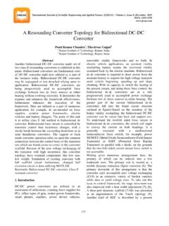
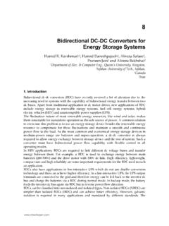
3 DC-DC converters for xEV aretypically benchmarked with respect to efficiency. xEVs requirea high efficiency over a wide range of operating points thatare defined by city and highway driving cycles. A promisingsolution is the Three-Level DC-DC converter [14], [15] that iscapable of operating at high efficiency over wide load and highvoltage transformation ranges. In particular, this converter hasbeen shown to be highly competitive when compared to thetwo-level and two-level inverterleaved converters [16].This paper proposes a novel modeling and control ap-proach for the Three-Level DC-DC converter . The converteris described in a sum and difference ( ) framework. It isshown that the formulation is useful to model the inverter andderive design specific equations. Design equations are givenfor balanced operation and can be easily extended to unbal-C1C2S1S2S3S4+++v1v2 CbvbLiLIbId+vd+vsic1ic2 Fig. 1: Three-Level DC-DC operation.
4 The results are confirmed by simulation. Theconverter is operated in both two- and Three-Level latter introduces vertical interleaving to reduce passivecomponents. It is proven that the passive components can bereduced by50%to75%using Three-Level operation. The sameratio holds when comparing the 2L DC-DC (conventionalbuck-boost converter ) to the 3L DC-DC framework is further used for control. It canbe used in a fashion similar to thedqframework that iswidely employed in motor drives [17]. The component isresponsible for current control, the power flow, whereas the system is used to control the voltage sharing of the DC-link capacitors. It is shown that there are cross-coupling termsbetween the and axes and that they can be is optional and can be taken care of by asufficiently fast feedback controller. The control is verified byintroducing load current and DC voltage steps in high ANALYSISThe Bidirectional Three-Level boost converter has four usefulswitching states.
5 One of the upper two switches (S1andS2)needs to be off to avoid short-circuiting the voltagev1(t).TABLE I: Switching states, capacitor currents and outputvoltages for the Three-Level (t)[ic1,ic2] vs(t)offononoff[0,0] [0,0] 0onoffonoff[1,0] [ iL,0] v1offonoffon[0,1] [0, iL] v2onoffoffon[1,1] [ iL, iL] v1+v2978-1-5090-3953-1/$ 2017 IEEE 573 Likewise, one of the lower two switches (S3andS4) needsto be off to avoid short-circuiting the voltagev2(t). TurningbothS1andS2(orS3andS4) off yields a voltage,vs(t), thatdepends on the sign of the current and is ignored in this resulting useful switching states are shown in Table I andFig. simplify the modeling , we introduce the binary switchingstates(t) = [s1(t),s2(t)] {0,1}2and capacitor voltagev12(t) = [v1(t),v2(t)] R2+, wherevd(t) =1 v12(t) =v1(t) +v2(t) R+. Hence, the voltage that is applied tothe inductor isvs(t) =v12(t) s(t) R+. In practice, DC-DCconverters are typically designed forPulse Width Modulation(PWM).
6 PWM translates a duty cycled= [d1,d2] [0,1]2into a switching sequence with time averaged=1 Tsw kTsw+TswkTsws(t)dt,(1)whereTswis the switching period. Similarly, the model canbe rewritten using average modeling (neglecting second ordercomponents)vs=v 12d=v1d1+v2d2.(2)Furthermore, we introduce the sum and difference notationd = [d ,d ] =Tdandv = [v ,v ] =Tv12, whereT=[111 1](3)andv =vd. The updated notation yieldsvs=(T 1v ) (T 1d )(4a)=12v d =12(vdd +v d ),(4b)and the (discrete-time) dynamic equation of the inductorcurrenti+L=iL+TsLvs TsLvb(5a)=iL+Ts2L(vdd +v d ) TsLvb,(5b)where the sampling periodTs=Tswfor simplicity and.+denotes entities of the (discrete) sampling time instantt+ voltages on capacitorsC1andC2vary as a function ofthe inductor current and duty cycle, perv+12=v12 TsCiLd+TsCId,(6)where we assumeC1=C2=Cfor simplicity andIdis theconstant DC current. This equation states thatd1>0andd2>0discharges the capacitorsC1andC2with currentiL,respectively.
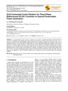
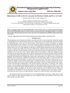
7 The duty cyclesd1= 0andd2= 0bypassiLanddo not affect the capacitor voltage. The equation is rewrittenusing the sum and difference notation asv+ =v TsCiLd +[2 TsCId,0] .(7)(a)s= [0,0] (b)s= [1,0] (c)s= [0,1] (d)s= [1,1] Fig. 2: Conduction paths as a function of the switching states(t).Adding the dynamic equation of the capacitorCb, we obtainthe full dynamics of the system in scalar notation:i+L=iL+Ts2L(vdd +v d ) TsLvb,(8a)v+ =v TsCiLd ,(8b)v+d=vd TsCiLd +2 TsCId,(8c)v+b=vb+TsCbiL TsCbIb;(8d)or, in matrix form,x+=Ax+B(x)u+e,(9)wherex= [iL,v ,vd,vb] is the state vector,u=d is theinput andeis the exogenous input. Their parameters areA= 1 0 0 TsL0 1 0 00 0 1 0 TsCb0 0 1 ,B(x) = Ts2 LvdTs2Lv 0 TsCiL TsCiL000 ,e= 002 TsCId TsCbIb .The system (9) has a constant state parameter matrix and isaffine in the input with a state-dependent parameter state-space system (8) defines the following controlproblems that need to be addressed to operate the three-levelDC-DC converter Power flow:the converter transfers the powerp= the power translates into controllingiLsincevbis approximately constant (by design or control).
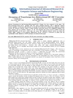
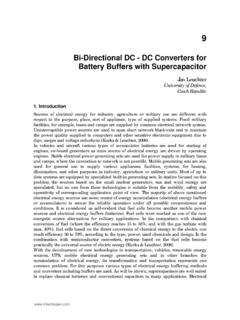
8 Symmetric operation:Converters are typically imple-mented with one type of semiconductor and minimize component stresses, the capacitor voltagesshould be symmetrical, which can be achieved by con-trollingv to zero. Voltage stabilization:Eithervborv12can be controlledvia the power flow through the converter . The othervoltage needs to be stabilized via the exogenous input(IborIc) since the converter cannot store significantamounts of energy. Stabilization can be achieved throughconnection to a DC bus or energy storage system (batteryor ultracapacitor). [V]020040001020iL[A]40506001020ic[A]0500 1020vc[V]19820020201020vd[V]395400405t [us ]01020vb[V] (a) No interleaving,d1= [V]020040001020iL[A]40506001020ic[A]0500 1020vc[V]19820020201020vd[V]395400405t [us ]01020vb[V] (b) Interleaving,d1= [V]020040001020iL[A]40506001020ic[A]0500 1020vc[V]19820020201020vd[V]395400405t [us ]01020vb[V] (c) No interleaving,d1= [V]020040001020iL[A]40506001020ic[A]0500 1020vc[V]19820020201020vd[V]395400405t [us ]01020vb[V] (d) Interleaving,d1= 3: High fidelity simulations, with and without interleaving, forC1=C2=Cb= 30 F,L= 47 H andfsw= , vd [pu] [pu] ^_^vb [pu]_^Fig.
9 4: Normalized current and voltage ripples. Continuousline: analytic functions (12), (13), (15), (16), (18) and (19);markers: current ( ) and voltage ( ) ripples obtained fromhigh fidelity simulation withC1=C2=Cb= 30 F,L=47 H andfsw= MODULATIONThe upper bridge (switchesS1andS2) is actuated bythe duty cycled1and the lower bridge (S3andS4) byd2using dedicated PWM modules. Both bridges can be operatedindependently from one another and two modulation strategiesare analyzed: two-level (2L) and Three-Level (3L) PWM carrier signals of the upper and lower bridge are inphase for 2L switching and phase shifted by180 (Tsw/2)in 3L switching. Three-Level switching can be interpretedas a verticalinterleavingof the two bridges. Interleavingis generally considered to reduce current (voltage) ripplescompared to 2L switching. An example is shown in switching ripples are analyzed in steady state condi-tions.
10 Substitutingi+L=iLandv+ =v in (28) yieldsvs=vbandi = 0, = 0, andd1=d2=d /2 = also assume symmetric operation, wherev = 0andv1=v2=vd/2. This operation yields symmetric voltageand current stresses on the upper and lower bridge and it canbe shown that it yields minimum ripples. In these conditions,it can be shown that the (constant) input/output currents areIc=d1iLandIb= 2L and 3L switching yield a characteristic switchingpattern in the steady state that can be observed in Fig. 3. Two-level switching only applies the switching statess(t) = [0,0] ands(t) = [1,1] such thatvs(t)switches between two voltagelevels:0 Vandvd. In contrast, 3L switching applies all fourswitching states andvs(t) {0V,vd/2,vd}. Dependent on theduty cycle,vsswitches between0 Vandvd/2 addition, 3L switching effectively doubles the switchingfrequency for the passive quantify the effects of switching, we formally definethe switching ripple as the peak-to-peak amplitude overTswin steady state conditions.