Transcription of Bi-Directional DC - DC Converters for Battery Buffers with ...
1 9. Bi-Directional DC - DC Converters for Battery Buffers with Supercapacitor Jan Leuchter University of Defence, Czech Republic 1. Introduction Sources of electrical energy for industry, agriculture or military use are different with respect to the purpose, place, sort of appliance, type of supplied systems. Fixed military facilities, for example, bases and camps are supplied by common electrical network system. Uninterruptible power sources are used to span short network black-outs and to maintain the power quality supplied to computers and other sensitive electronic equipment due to dips, surges and voltage reductions (Kurka & Leuchter, 2008). In vehicles and aircraft various types of accumulator batteries are used for starting of engines, on-board generators as main source of electrical energy are driven by operating engines.
2 Stable electrical power generating sets are used for power supply in military bases and camps, where the connection to network is not possible. Mobile generating sets are also used for general use to supply various appliances, facilities, systems, for heating, illumination, and other purposes in industry, agriculture or military units. Most of up to date systems are equipped by specialized built-in generating sets. In studies focused on this problem the sources based on the small nuclear generators, sun and wind energy are speculated, but no one from these technologies is suitable from the mobility, safety and operativity of corresponding application point of view. The majority of above mentioned electrical energy sources use some means of energy accumulation (electrical energy Buffers or accumulators) to secure the reliable operation under all possible circumstances and conditions.
3 It is considered as self-evident that fuel cells become another mobile power sources and electrical energy Buffers (batteries). Fuel cells were marked as one of the new energetic source alternatives for military applications. In the comparison with classical conversion of fuel (where the efficiency reaches 15 to 35%, and with the gas turbine with max. 40%), fuel cells based on the direct conversion of chemical energy to the electric one reach efficiency 50 to 70%, according to the type, power, used chemicals and design. In the combination with semiconductor Converters , systems based on the fuel cells become practically the universal source of electric energy (Kurka & Leuchter, 2008).
4 With the development of new technologies in transportation, vehicles, renewable energy sources, UPS, mobile electrical energy generating sets and in other branches the accumulation of electrical energy, its transformation and transportation represents one common problem. For this purposes various types of electrical energy buffering methods and Converters including Buffers are used. As will be shown, supercapacitors are well suited to replace classical batteries and conventional capacitors in many applications. Electrical 180 Energy Storage in the Emerging Era of Smart Grids energy generating sets (EGS) still are and will probably be in near future based mainly on generators driven by combustion engines using fossil fuels.
5 EGS initially developed and produced mainly for military purposes because EGS enable the independence on the common electrical power network. They are used in ground and air transport, in health service and in other military branches. The EGS are quite indispensable in civil defence, crisis management forces, and naturally in security forces. Sophisticated weapon systems, including aircraft and air defence, artillery systems, transport means, logistical structure and training systems based on computer simulation and virtual reality concepts, require also modern and reliable EGS, corresponding to new conditions and requirements. In order to increase efficiency, decrease the fuel consumption and optimize the operational conditions of mobile electrical power generating sets, the VSCF (variable speed-constant frequency).
6 Technology is used. Variable output voltage and frequency are transformed to constant values by means of power electronic Converters . Due to unconvenient dynamical properties of VSCF based EGS the electrical energy Buffers (accumulators) create the essential part of the system securing its reliable operation and can help improve a dynamic behaviour of diesel engine which is limited mainly by fuel injecting. (Kurka & Leuchter, 2008 and 2000). and (Leuchter et al., 2009). In the following pages we shall propose the energy buffer of EGS with VSCF technology to illustrate the feature, requirements and advantages of systems with energy buffer. EGS with optimum variable speed is really fine example, where power buffer can improve dynamic behaviour, improve efficiency, and reduce volume.
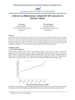
7 2. Electrical power buffer A simplified block diagram of an electrical generator sets (EGS) with variable speed control can be seen in Figure 1, where a represent actual engine speed and o optimum engine speed. As a consequence of varying the engine speed when using the optimum variable speed control, both the output voltage and the output frequency of the generator vary and must be regulated to a constant value as required by the load. Therefore, a power electronic converter is required to regulate the output voltage and frequency. The real drawback of the concept with optimum variable speed is the inferior engine-generator dynamics. In case of sudden power output increase, the engine can not deliver the requested torque and the result is further decrease of the speed and torque of the engine until the undesirable stop.
8 The diesel engine has namely a time constant of few seconds, which is further limited by fuel injection limitation. Therefore at high change of the speed the engine undesirably stops. This problem of the EGS dynamic behaviour can be improved by means of electrical power buffer. The engine-generator dynamics, poses during sudden transients from low-load to high-load conditions, still poses a challenge in this regard. (Leuchter et al., 2010). The dynamic behavior analyses of 4 kW EGS with kW diesel engine can be summarized to the figure 2. Thus, we see that output power of engine depends on engine speed. We now can describe three types of power for every engine speed. The first power can be denoted as Popt, which represents the power provided by engine operating at the optimal angular speed to achieve the minimum fuel consumption.
9 The second PLmax represents a maximum power that can be obtained for every speed. If the load power is higher then PLmax then the engine cannot deliver the requested torque and the result is further decrease of the speed and torque of the engine until the undesirable stop. For carrying out the successful speed change, PLmax must be higher than power required by the load the condition PL2 < PLmax Bi-Directional DC - DC Converters for Battery Buffers with Supercapacitor 181. must be fulfilled. The third curve Prez is the difference between PLmax and Popt and it indicates the reserve of power of the system operating at optimal angular speed. For example: if the engine operates with an angular speed of 150 rad s-1 then the output power of engine is 1900 W and the power margin of engine is as high as 1700 W.
10 If the power increase is higher, then the diesel engine cannot develop enough power required by the load. (Leuchter et al., 2009). variable; PL1 f variable f constant; PL2. Diesel SGPM PE Load engine a o Controller Iload Fig. 1. Block diagram of EGS system with VSCF technology (SGPM-synchronous generator with PM; PE-power electronics). PL. Pmax P. [W] L max Popt Prez [rad/s]. Fig. 2. Identification of the power margin (Diesel engine Hatz 1D40; kW). A power buffer, connected via an electronic converter , can improve the dynamic behaviour of the system with diesel engine by means of injecting stored energy into the dc-link by the dc-dc converter , see Fig. 3. This concept is based on the delivery of peak power from the energy storage to the link capacitor of the dc-dc converter during the low to high speed transition of the diesel engine.