Transcription of Binary Phase Shift Keying (BPSK) Lecture Notes 6: Basic ...
1 Lecture Notes 6: Basic Modulation SchemesIn this Lecture we examine a number of different simple modulation schemes. We examine theimplementation of the optimumreceiver, the error probabilityand the wouldlike the simplest possible receiver, withthe lowest error probabilityand smallestbandwidthfor a given data Binary Phase Shift Keying (BPSK) The first modulation considered is Binary Phase Shift Keying . In this scheme during every bitduration, denoted byT, one of two phases of the carrier is transmitted. These two phases are180 degrees apart. This makes these two waveforms antipodal.
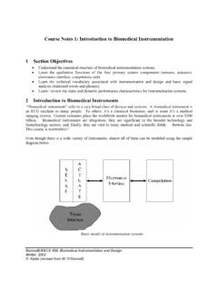
2 Any Binary modulation wherethe two signals are antipodal gives the minimumerror probability(for fixed energy) over anyother set of Binary signals. The error probabilitycan onlybe made smaller (for fixed energyper bit)by allowing more than two waveforms for transmitting BPSKM odulator b t 2 Pcos 2 fct Modulator s t n t r t Figure 33: Modulator for BPSKTo mathematicallydescribed the transmitted signal we define a pulse functionpT t aspT t 1 0 t T0 otherwise. t1pT t TLetb t denote the data waveformconsisting of an infinitesequence of pulses of durationTVI-3 and height t l blpT t lT bl 1 1!
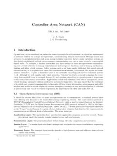
3 "The transmitted signal then is given bys t 2P l blcos 2 fct pT t lT 2P b t cos 2 fct 2 Pcos 2 fct t where t is the Phase waveform. The signal power isP. The energy of each transmitted bitisE Phase of a BPSK signal can take on one of two values as shown inFigure b t T2T3T4T5T1-1t t T2T3T4T5T 0tFigure 34: Data and Phasewaveformsfor BPSKVI-5 r t 2 Tcos 2 fct LPF X iT t iT 0 decbi 1 1 0 decbi 1 1 Figure 35: Demodulator for BPSKThe optimumreceiver for BPSK inthe presence of additive whiteGaussian noise is shown inFigure VI-3. The low pass filter (LPF) is a filter matched tothe baseband signal beingtransmitted.
4 For BPSK this is just a rectangular pulse of durationT. The impulse response ish t pT t "The output of the low pass filter isX t 2 Tcos 2 fc h t r d "VI-6 The sampled version of the output is given byX iT 2 Tcos 2 fc pT iT r d iT i 1 T 2 Tcos 2 fc 2P b cos 2 fc n d iT i 1 T2 P T bi 1cos 2 fc cos 2 fc d i" iis Gaussian randomvariable, mean 0 varianceN0 2. Assuming 2 fcT 2 nfor someintegern(or thatfcT 1)X iT PT bi 1 i E bi 1 i"VI-7 X(iT)PPe,+1e,-1EE0 Figure 36: ProbabilityDensityof Decision Statisticfor Binary PhaseShiftKeyingVI-8 Bit Error Probability of BPSKPe b Q 2EN0 Q 2 EbN0 whereQ x x12 e u2 2duFor Binary signals this is the smallest bit error probability, BPSK are optimal signals andthe receiver shown above is optimum(inadditive whiteGaussian noise).
5 For Binary signalsthe energy transmitted per information bitEbis equal tothe energy per signalE. ForPe b 10 5we need a bit-energy,Ebtonoise densityN0ratioofEb N0 9" :Q x is a decreasing function which is 1/2atx 0. There are efficient algorithms (based on Taylorseries expansions) tocalculateQ x . SinceQ x e x2 2 2 the error probabilitycan beupper bounded byPe b 12e Eb N0 which decreases exponentiallywithsignal-to-noise 161412108642010-10 Error Probability of BPSKEb/N0(dB)Pe,b10-910-810-710-610-510- 410-310-210-11 Figure 37: Error Probabilityof Bandwidth of BPSKThe power spectral densityis a measure of the distribution of power withrespect power spectral densityfor BPSK has the formS f PT2 sinc2 f fc T sinc2 f fc T wheresinc x sin x x"Notice that S f d f P"The power spectrumhas zeros or nullsatf fc i Texcept fori 0.
6 That is there is a null atf fc 1 Tcalled the first null;a null atf fc 2 Tcalled the second null;etc. Thebandwidthbetween the first nullsis called the null-to-null bandwidth. For BPSK thenull-to-null bandwidthis 2 T. Notice that the spectrumfallsoff as f fc 2asfmoves awayfromfc. (The spectrumof MSK fallsoff as the fourthpower, versus the second power forBPSK).It is possible toreduce the bandwidthof a BPSK signal by filtering. If the filtering is doneproperlythe (absolute) bandwidthof the signal can be reduced to1 Twithout causing anyintersymbol interference; that is all the power is concentrated inthe frequency rangeVI-11 1 2T f fc 1 2T.
7 The drawbacks are that the signal loses itsconstant envelopeproperty(useful for nonlinear amplifiers) and the sensitivitytotiming errors is greatlyincreased. The timing sensitivityproblemcan be greatlyalleviated by filtering toa slightlylarger bandwidth 1 2T f fc 1 2T .VI-12 (f)-4-3-2-101234(f-fc)TFigure 38: Spectrumof BPSKVI-13 -100-80-60-40-200S(f) (dB)-5-4-3-2-1012345(f-fc)TFigure 39: Spectrumof BPSKVI-14 -100-80-60-40-200S(f) (dB)-10-8-6-4-20246810(f-fc)TFigure 40: Spectrumof BPSKVI-15 ExampleGiven: Noise power spectral densityofN0 2 180 dBm/Hz =10 21 Watts/Hz.
8 Pr 3 10 13 Watts DesiredPe 10 :The data rate that can be used and the bandwidththat is :NeedQ 2Eb N0 10 7orEb N0 11"3dB orEb N0 13"52. ButEb N0 PrT N0 13"52. Thus the data bit must be at leastT 9"0 10 8seconds long, data rate 1 Tmust be less than 11 Mbits/second. Clearlywe also need a (null-to-null)bandwidthof 22 alternative view of BPSK is that of two antipodal signals; that iss0 t E t 0 t Tands1 t E t 0 t Twhere t 2 Tcos 2 fct 0 t Tis a unit energy waveform. The above describesthe signals transmitted onlyduring the interval 0 T . Obviouslythis is repeated for otherVI-16 intervals.
9 The receiver correlates with t over the interval 0 T and compares withathreshold(usually0) tomake a decision. The correlation receiver is shown below. r t t T0 decs0 decs1 This is called the Correlation Receiver. Note that synchronization tothe symbol timing andoscillator Phase are Effect of FilteringandNonlinear Amplificationon a BPSK waveformIn this section we illustrate one maindrawback toBPSK. The fact that the signal amplitudehas discontinuities causes the spectrumtohave fairlylarge sidelobes. For a systemthat has aconstraint on the bandwidththis can be a problem.
10 A possible solution is tofilter the signal. Abandpas filter centered at the carrier frequency which removes the sidbands can be insertedafter mixing tothe carrier frequency. Alternatlywe can filter the data signal at basebandbefore mixing tothe carrier we simulate this type of systemtoillustrate the effect of filtering and nonlinearamplification. The data waveformb t is mixed ontoa carrier. This modulated waveformisdenoted bys1 t 2 Pcos 2 fct The signals1 t is filtered by a fourthorder bandpass Butterworthfilter withpassband fromfc 4 Rbtofc 4 RbThe filtered signal is denoted bys2 t.